Category Archives: Administration Guides

FortiWAN – System Configurations

System Configurations

This topic elaborates on [System] and its submenus. Simple examples are given to illustrate how to configure [system] settings.

Summary

As soon as you log in to the web UI, you will see the [System/Summary].It shows you basic information on the system, including [System Information], [Peer Information],and [WAN Link State]. [Peer Information] is populated as soon as HA mode becomes active. As is mentioned in “FortiWAN in HA (High Availability) Mode”, HA (High Availability) is hot backup. In HA mode, one FortiWAN is the primary system while the other is the backup system.

System Information / Peer Information

System Information

Version : The firmware version of the device.
Model/Max Bandwidth (Total RAM) : The model of the device and the bandwidth capability that the model supports. You can purchase a license for higher bandwidth capability from your Fortinet channel partner (See subsection “License Control” in “Administration”). For deployment of FortiWAN-VM, the Total RAM is displayed here rather than Max Bandwidth.
Serial Number : The serial number of the device.
Uptime : The time the device has been up and running.
Connections : The number of connections.
CPU Usage % : The CPU usage in percentage.
Packets/Second : The number of the packets that are processed per second.
VRRP State : The state of VRRP (Virtual Router Redundancy Protocol) – whether it is enabled. Note: When VRRP is enabled, HA will be disabled, and vice versa. (See “LAN Private Subnet”)
Hard Disk : FortiWAN’s hard disk for Reports is being consumed by increasing report database. Once the disk space is used up, Reports will fail to continue log processing. This field monitors the disk space status of Reports by displaying the total space and consumed space. (See “Reports”)


License Status

Peer Information

: This field is visible only when the model is FortiWAN-VM. This field displays the status of a FortiWAN-VM license as follows:

Trial License is in use. (Expire in x days x hours x mins): This is a trail or evaluation license.

Valid: This is a permanent license.

Expired: This license is expired.

Click Update button and upload your FortiWAN-VM license file to update your FortiWAN-VM appliance. You can request a evaluation or trial license from Fortinet Customer Support or you can purchase a permanent license from your Fortinet channel partner.

Version : The firmware version of the slave.
Model/Max Bandwidth : The model of the slave and the bandwidth capability that the model supports. For deployment of FortiWAN-VM, only the model of the slave is displayed here, no Max Bandwidth and Total RAM.
Serial Number : The serial number of the slave.
Uptime : The time the slave has been up and running.
State : Normally, this field displays “Slave”.

During the procedure of reboot, this field displays “Rebooting“.

System panic happens, this field displays “Panic“.

Peer unit is lost (power-off or Ethernet cable disconnected), this field displays “None“.

Firmware version, FortiWAN model or throughput license is

inconsistent with the local unit, this field displays “Incompatible“.

Note1: Connections may exceed 100 when FortiWAN is started, but will return to normal in a while. This happens because FortiWAN sends out ICMP packets to test the network.

Note2: Once HA becomes active, settings of master unit will be synchronized to slave unit automatically.

WAN Link State

[WAN Link State] shows you the number of WAN links enabled and their current status. The number of WAN links available for each FortiWAN may vary depending on models. In [WAN Link State], each WAN link is color-coded to indicate its status. See the color-coding scheme below:


l Green: Active WAN link l Blue: Backup WAN link l Red: Failed WAN link

WAN Link State

WAN : Enabled WAN Link.
State : Current connection status.
IPv4 / IPv6 Address : The IPv4 or IPv6 address of the WAN port (See “Configuring your WAN”).
Note The notes for the WAN link (See “Configuring your WAN”).

Get system information, peer information and WAN link state via SNMP

You can use SNMP manager to get the system information, HA peer information and WAN link state. Configure SNMP for your FortiWAN unit (See “SNMP”) and you can get the information in a MIB field via SNMP manager. The correspondent MIB fields and OIDs are listed as following:

SNMP field names and OIDs

MIB Field OID Description
fwnSysSlaveVersion 1.3.6.1.4.1.12356.118.1.2 Firmware version of the slave unit deployed with this local unit in HA mode.
fwnSysSlaveSerialNumber 1.3.6.1.4.1.12356.118.1.3 Serial number of the slave unit deployed with this local unit in HA mode.
fwnSysSlaveUptime 1.3.6.1.4.1.12356.118.1.4 Uptime of the slave unit deployed with this local unit in HA mode.
fwnSysSlaveState 1.3.6.1.4.1.12356.118.1.5 State of the slave unit deployed with this local unit in HA mode.
fwnSysConnections 1.3.6.1.4.1.12356.118.1.6 Number of connections that are being processed in the system.
fwnSysCpuLoad 1.3.6.1.4.1.12356.118.1.7 Current CPU load (in percentage) of the system.
fwnSysUsers 1.3.6.1.4.1.12356.118.1.8 Number of IP addresses connecting to the FortiWAN unit from the LAN and DMZ subnets.
fwnSysPktPerSec 1.3.6.1.4.1.12356.118.1.9 Number of packets transferred via the system every second.


MIB Field OID Description
fwnSysConnectionRates 1.3.6.1.4.1.12356.118.1.10 Number of connections that are established with the FortiWAN unit every second.
fwnWanStatus 1.3.6.1.4.1.12356.118.2.1.2.1.3 State of every WAN link: ok(1), failed(2), disabled(3), backup(4) and unkown(5).
fwnWanIP 1.3.6.1.4.1.12356.118.2.1.2.1.4 First one of the IP addresses deployed on the WAN port

(localhost) of every WAN link.

See also

l FortiWAN in HA (High Availability) Mode l LAN Private Subnet l Configuring your WAN l Reports


Having trouble configuring your Fortinet hardware or have some questions you need answered? Check Out The Fortinet Guru Youtube Channel! Want someone else to deal with it for you? Get some consulting from Fortinet GURU!

MIB fields for WAN links and VLANs

MIB fields for WAN links and VLANs

You can use SNMP manager to get information of defined WAN links and VLANs and receive notifications when a WAN link fails or recovers. Configure SNMP for your FortiWAN unit (See “SNMP”) to get the information in a MIB field via SNMP manager. Configure the SNMP manager on your FortiWAN and enable the event types “” and “” to notify (See “Notification”), then notifications will be delivered to your SNMP manager for the events. The correspondent MIB fields and OIDs are listed as following:

SNMP field names and OIDs for WAN link

MIB Field OID Description
fwnWanNumber 1.3.6.1.4.1.12356.118.2.1.1 Maximum of WAN links that the system supports.
fwnWanTable 1.3.6.1.4.1.12356.118.2.1.2 This is a table containing one element of object fwnWanEntry used to describe the properties and management information of every WAN link deployed on the system
fwnWanEntry 1.3.6.1.4.1.12356.118.2.1.2.1 An object used to describe the properties and management information of every WAN link deployed on the system: Index, Descr, Status, IP, HealthReq,

HealthRep, UpLimit, DownLimit,

ConnTime, InOctets, OutOctets, TotalOctets, InOctets64,

OutOctets64 and TotalOctets64.

fwnWanIndex 1.3.6.1.4.1.12356.118.2.1.2.1.1 Index (unique positive integer) of every WAN link.
fwnWanDescr 1.3.6.1.4.1.12356.118.2.1.2.1.2 Label of every WAN link, such as WAN1, WAN2, WAN3, ect.
fwnWanStatus 1.3.6.1.4.1.12356.118.2.1.2.1.3 State of every WAN link: ok(1), failed(2), disabled(3), backup(4) and unkown(5).
fwnWanIP 1.3.6.1.4.1.12356.118.2.1.2.1.4 First one of the IP addresses deployed on the WAN port

(localhost) of every WAN link.

fwnWanHealthReq 1.3.6.1.4.1.12356.118.2.1.2.1.7 Number of health detection (ping packets or TCP connect requests) sent out for every WAN link.
fwnWanHealthRep 1.3.6.1.4.1.12356.118.2.1.2.1.8 Number of acknowledgements replied to every WAN link for the health detection.
fwnWanUpLimit 1.3.6.1.4.1.12356.118.2.1.2.1.9 Maximum upload speed (in kbps) of every WAN link.


MIB Field OID Description
fwnWanDownLimit 1.3.6.1.4.1.12356.118.2.1.2.1.10 Maximum download speed (in kbps) of every WAN link.
fwnWanConnTime 1.3.6.1.4.1.12356.118.2.1.2.1.12 The time period that a WAN link has been available since the last recovery from failure or disability.
fwnWanInOctets 1.3.6.1.4.1.12356.118.2.1.2.1.5 Number (32bit unsigned integer) of octets received on the interface (RX) of every WAN link during system’s uptime.
fwnWanOutOctets 1.3.6.1.4.1.12356.118.2.1.2.1.6 Number (32bit unsigned integer) of octets transmitted from the interface (TX) of every WAN link during system’s uptime.
fwnWanTotalOctets 1.3.6.1.4.1.12356.118.2.1.2.1.11 Sum (32bit unsigned integer) of octets received and transmitted on/from the interface (RX and TX) of every WAN link during system’s uptime.
fwnWanInOctets64 1.3.6.1.4.1.12356.118.2.1.2.1.13 Number (64bit unsigned integer) of octets received on the interface (RX) of every WAN link during system’s uptime.
fwnWanOutOctets64 1.3.6.1.4.1.12356.118.2.1.2.1.14 Number (64bit unsigned integer) of octets transmitted from the (TX) interface of every WAN link during system’s uptime.
fwnWanTotalOctets64 1.3.6.1.4.1.12356.118.2.1.2.1.15 Sum (64bit unsigned integer) of octets received and transmitted on/from the interface (RX and TX) of every WAN link during system’s uptime.
fwnEventWanLinkRecovery 1.3.6.1.4.1.12356.118.2.2.2.1.1 Index of a WAN link will be sent as an event notification when the

WAN link recovers from a failure.

fwnEventWanLinkFailure 1.3.6.1.4.1.12356.118.2.2.2.1.2 Index of a WAN link will be sent as an event notification when the WAN link fails.

SNMP field names and OIDs for VLAN

MIB Field OID Description
fwnVlanNumber 1.3.6.1.4.1.12356.118.2.2.1 Number of VLAN defined on the system.
fwnVlanTable 1.3.6.1.4.1.12356.118.2.2.2 This is a table containing one element of object fwnVlanEntry used to describe the properties and management information of every

VLAN defined on the system

fwnVlanEntry 1.3.6.1.4.1.12356.118.2.2.2.1 An object used to describe the properties and management information of every VLAN defined on the system
fwnVlanDescr 1.3.6.1.4.1.12356.118.2.2.2.1.1 Label of every VLAN. It consists of the port that the VLAN is defined on and the VLAN tag, such as port1.101, port1.102, port2.203, ect.
fwnVlanInOctets 1.3.6.1.4.1.12356.118.2.2.2.1.2 Number (32bit unsigned integer) of octets received on the interface (RX) of every VLAN during system’s uptime.
fwnVlanOutOctets 1.3.6.1.4.1.12356.118.2.2.2.1.3 Number (32bit unsigned integer) of octets transmitted from th interface (TX) of every VLAN during system’s uptime.
fwnVlanTotalOctets 1.3.6.1.4.1.12356.118.2.2.2.1.4 Sum (32bit unsigned integer) of octets received and transmitted on/from the interface (RX and TX) of every VLAN during system’s uptime.
fwnVlanInOctets64 1.3.6.1.4.1.12356.118.2.2.2.1.5 Number (64bit unsigned integer) of octets received on the interface (RX) of every VLAN during system’s uptime.
fwnVlanOutOctets64 1.3.6.1.4.1.12356.118.2.2.2.1.6 Number (64bit unsigned integer) of octets transmitted from the interface (TX) of every VLAN during system’s uptime.


MIB Field OID Description
fwnVlanTotalOctets64 1.3.6.1.4.1.12356.118.2.2.2.1.7 Sum (64bit unsigned integer) of octets received and transmitted on/from the interface (RX and TX) of every VLAN during system’s uptime.
fwnVlanIndex 1.3.6.1.4.1.12356.118.2.2.2.1.8 Index (unique positive integer) of every VLAN.


Having trouble configuring your Fortinet hardware or have some questions you need answered? Check Out The Fortinet Guru Youtube Channel! Want someone else to deal with it for you? Get some consulting from Fortinet GURU!

Deployment Scenarios for Various WAN Types

Deployment Scenarios for Various WAN Types

This Section provides various network scenarios for the different WAN types and explains how FortiWAN can easily be integrated into any existing networks.

WAN Type: Bridge Mode with a Single Static IP

Single Static IP is a common and simple WAN network scenario, where the ISP provides a single public static (fixed) IP for the WAN link. Note: ISP often provides ATU-R, sometimes known as ADSL Modems with bridge model.

In this example it is assumed that WAN port 1 is connected to the bridge-mode ATU-R.

Please refer to the ATU-R User manual provided by your ISP to connect the ATU-R to FortiWAN’s WAN #1. Connect LAN to FortiWAN’s LAN port via a switch or hub. In this example, FortiWAN’s Port2 is treated as LAN port. Please map FortiWAN’s LAN port to the Port2 in [System] → [Network Setting] → [VLAN and Port Mapping]. Note: FortiWAN is treated as a normal PC when connecting to other networking equipments.

WAN configuration:

  1. Enter FortiWAN’s Web-based UI.
  2. Go to [System] → [Network Setting] → [WAN Settings].
  3. In the WAN LINK scroll menu, select “1”, and choose “Enable” in the Basic Settings.
  4. In the WAN type scroll menu, select [Bridge Mode: One static IP].
  5. Select [Port 1] in the WAN Port field.
  6. Enter the up/down stream bandwidth associated with this WAN link. Example: If the ADSL Line on WAN1 is 512/64, then enter [64] and [512] in the Up Stream and Down Stream fields respectively. Note: The up/down stream values entered will ONLY affect the BM and statistics reporting. Bandwidth will not increase if the values are greater than the actual bandwidth.
  7. Enter [211.100.3.35] in the Localhost IP field.
  8. Enter [255.255.255.0] in the Netmask field.
  9. Enter [211.100.3.254] in the Default Gateway IP field.
  10. Apply the bridge mode configuration.
  11. If the configuration above has been correctly established, in the [System] →[Summary] page, the status color on the WAN Link State for WAN Link #1 will turn green.

LAN configuration:

  1. Go to [System] → [Network Setting] → [LAN Private Subnet].
  2. Enter [192.168.1.254] in the IP(s) on Localhost field.
  3. Enter [255.255.255.0] in the Netmask field.
  4. Select [Port2] in the LAN Port field.
  5. Check NAT Subnet for VS.
  6. Configuration complete.

Virtual Server Configuration:

Assume an SMTP server with IP 192.168.1.1 provides SMTP services to the outside via the virtual server. FortiWAN will perform NAT on this machine so that the outside clients can get SMTP services via FortiWAN’s public IP on WAN1. The settings for this are in [Service] → [Virtual Server].

  1. Click [+] to create a new rule.
  2. Check [E] to enable this rule.
  3. Select [All-Time] in the “When” field.
  4. Enter [211.100.3.35] in the WAN IP field.
  5. Select [SMTP(25)] in the Service field.
  6. Select [Round-Robin] in the Algorithm field.
  7. Click [+] to create a new server in Server Pool.
  8. Enter [192.168.1.1] in the Server IP field.
  9. Select [SMTP(25)] in the Service field.
  10. Enter [1] in the Weight field.
  11. Selection of the L field is optional. (If an Administrator wishes to log Virtual Server activities, please select “L”).
  12. Configuration complete.

Administrators can set up different types of services inside the LAN and use the Virtual Server to make these services available to public once the configurations are completed.


Having trouble configuring your Fortinet hardware or have some questions you need answered? Check Out The Fortinet Guru Youtube Channel! Want someone else to deal with it for you? Get some consulting from Fortinet GURU!

Automatic addressing within a basic subnet

Automatic addressing within a basic subnet

FortiWAN functions for various network topologies which consists of connectivity of multiple subnets (basic subnet). Deployments of basic subnets varies for purposes, but they can be simply divided, according to the location, into three basic types: WAN-sided subnet, DMZ-sided subnet and LAN-sided subnet, which are supposed to connect to the WAN port, DMZ port and LAN port of FortiWAN. FortiWAN so that services the hosts in the subnets. For this reason, mechanisms to automatically address the hosts in those basic subnets are provided. FortiWAN’s automatic addressing is designed to serve the hosts in DMZ-sided and LAN-sided subnets. Hosts in WAN-sided subnets can only be addressed manually. DMZ-sided subnets are divided further into Subnet-in-DMZ, and Subnet-in-WAN-and-DMZ. FortiWAN’s automatic addressing is designed according to IPv4 network and IPv6 network, which is described as follows:

IPv4 Automatic addressing

FortiWAN provides standard DHCP and DHCP Relay to allocate IPv4 addresses to or relay DHCP messages for hosts in the following subnets or IP range:

DMZ Side l 
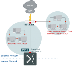
Routing Mode, IPv4 Basic Subnet: Subnet in DMZ
  l 
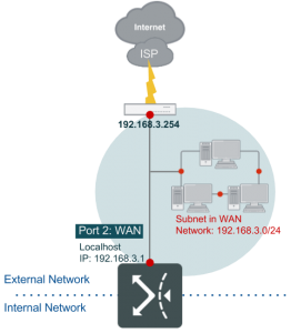
Routing Mode, IPv4 Basic Subnet: Subnet in WAN and DMZ
  l 
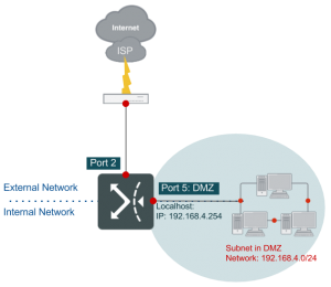
Bridge Mode: Multiple Static IP, IPv4 IP(s) in DMZ
LAN Side l LAN Private Subnet

DHCP

FortiWAN acts a DHCP server on the specified LAN port or DMZ port if checkbox Enable DHCP is checked. FortiWAN receives DHCP requests and responds related information from/to hosts (DHCP clients) in the subnets connect to the LAN or DMZ ports.

Domain Name Server   The DNS that FortiWAN responds to the DHCP clients within the DHCP OFFER messages if the clients are sat to automatically get DNS information through DHCP.
  l Single DNS server: the DNS servers defined in System > Network

Setting > DNS Server > IPv4 Domain Name Server are listed here for your options.

  l ALL: answer the DHCP clients with all the defined DNS servers information.
  l None: answer the DHCP clients without containing any DNS server information.

This option is only available for LAN private subnet. For the DMZsided subnets (hosts in the two subnets are supposed to be deployed with public IP addresses), system behaves answering the DHCP clients with all the defined DNZ servers information.

Domain Name Suffix   The domain name suffix that FortiWAN responds to the DHCP clients within the DHCP OFFER messages if the clients are sat to automatically get DNS information from DHCP.
  l Single domain name suffix: the domain name suffixes defined in System > Network Setting > DNS Server > Domain Name Suffix are listed here for your options.
  l ALL: answer the DHCP clients with all the defined domain name suffixes.
  l None: answer the DHCP clients without containing any domain name suffixes.

This option is only available for LAN private subnet.


TFTP Server Name This option is used to deliver a TFTP server name to DHCP clients.

When the DHCP server see the request in a DHCP discover from a DHCP client, it returns the TFTP server name in its DHCP offer to the client as DHCP option 66. Usually, option 66 is used for IP phone auto-provisioning. You will need to refer to a vender’s documentation to configure this option.

Specify the IP address or the hostname of a TFTP server directly here according to what the device vender provides. FortiWAN DHCP will directly return what is specified here to requests without any encoding/decoding. The DHCP server will ignore the request for option 66 from a DHCP client if this field is leaved blank. Note that FortiWAN does not support DHCP option 67 (Bootfile Name) and option 150 (TFTP Server Address).

Vendor Encapsulated Options This option is used to transmit Vender Specific Information between the DHCP server and clients. Usually, the information could be the configuration data to the DHCP clients. For example an IP address of a WLAN controller or a DLS (Deployment Service) server, or an identifier if the DHCP clients are wireless APs, IP phones or other devices. When the DHCP server see the request in a DHCP discover (option 43 or number 43 included in option 55) from a DHCP client, it returns the vender specific information in its DHCP offer to the client as DHCP option 43.

The vender encapsulated option ca contain either a single venderspecific value or multiple vender-specific sub-options. The RFC allows a vender to define its own sub-option codes. All the suboptions are included in the DHCP offer as Type-Length-Value blocks embedded within the option 43. You will need to refer to a vender’s documentation to form the options to their specification.

Specify the information directly here in hexadecimal numbering format according to what the device vender provides. FortiWAN DHCP will directly return what is specified here to requests without any encoding/decoding. The DHCP server will ignore the request for option 43 from a DHCP client if this field is leaved blank. Note that FortiWAN does not support DHCP option 60 (Vender Class Identifier), DHCP server will not return option 43 based on option 60.

DHCP Range The address pools that DHCP server assigns and manages IP addresses from. Define the IP ranges by specifying IPv4 Starting Address and IPv4 Ending Address.
Static Mapping DHCP server assigns and manages IP addresses according to clients’ MAC addresses. An IP address that is mapped to a MAC address is only available to the client with the MAC address. It will not be assigned to other client even it is idle. Define the mapping by specifying MAC Address and the correspondent IPv4 Address.
Client ID Mapping DHCP server assigns and manages IP addresses according to the client ID of DHCP client (the Client Identifier, options code 61, in the options field of DHCP request). An IP address that is mapped to a client ID here is only available to this client. It will not be assigned to other clients even it is idle. Define the mapping by specifying Client ID and the correspondent IPv4 Address. Corresponding setting of client ID on a DHCP client is required.

Note that IP addresses defined in DHCP Range, Static Mapping or Client ID Mapping must be also defined in filed IPv4 IP(s) in DMZ for a bridge-mode (multiple static IP) WAN link, the DMZ side of basic subnets (subnet in WAN and DMZ, and subnet in DMZ) for a routing-mode WAN link and the basic subnets of private LAN subnets.

DHCP Relay

DHCP relay is a proxy forwarding DHCP requests and responses between hosts and DHCP server across different subnets. A router called DHCP relay agent acts the proxy receiving DHCP requests from hosts in the same subnet and resending them to the DHCP server located in another subnet. The DHCP relay agent then delivers the DHCP messages responded by the DHCP server to the hosts in the subnet, so that the hosts are assigned the IP addresses and related information.

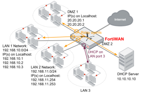
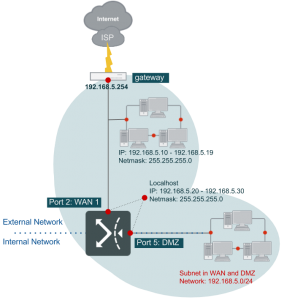
FortiWAN is the DHCP relay agent in the network once the DHCP Relay function is enable. Address allocation for multiple subnets (subnet in LAN, subnet in DMZ, subnet in WAN and DMZ and IPs in DMZ) can be managed by a centralized DHCP server. As the example below, FortiWAN relays the DHCP messages between the connected subnets and the standalone DHCP server, so that one DHCP server manages the address allocation for the three subnets, LAN 1, LAN 2 and a DMZ 1. As for subnet LAN 3, it employs FortiWAN’s DHCP server on LAN port 3. The enabled DHCP server on LAN port 3, which is independent from the standalone DHCP server, serves only subent LAN 3. Note that you can only enable either DHCP or DHCP Relay for a subnet.

To implement the deployment, you need to enable DHCP Relay for each of the subnets (enable DHCP Relay on each of the ports). In the example above, DHCP Relay is enabled on ports of LAN 1, LAN 2 and subnet in DMZ 1, and all the DHCP requests received on the ports will be forwarded to the DHCP server in the subnet DMZ 2. A LAN port or DMZ port with DHCP Relay being enabled on will forward the DHCP requests it received (coming from the subnet it connects to) to the DHCP server.

FortiWAN supports up to two DHCP servers in a DHCP relay deployment. Once two DHCP servers are configured, the relay agent will forward a DHCP request to both of the DHCP servers. The first response received by the relay agent will be first apply to the DHCP client, and the subsequent responses will be ignored then.

DHCP Relay Server 1 IP address of the first standalone DHCP server.
DHCP Relay Server 2 IP address of the second standalone DHCP server. Leave it blank if only one DHCP server is required for the DHCP relay deployment.
DHCP Relay Agent IP The IP address of the DHCP Relay agent on the port. It indicates the source of a relayed DHCP request to the DHCP server. This IP will be contained in a relayed DHCP message, so that the DHCP server could recognize the relay agent that the relayed DHCP request came from and respond the corresponding IP address to the DHCP client (according to this DHCP Relay Agent IP and the addressing policy).

The DHCP Relay Agent IP must be an IP address deployed on the localhost of the LAN port or DMZ port. You might deploy multiple IP addresses to a LAN port or a DMZ port (the field IP(s) on Localhost of a LAN subnet, a subnet in DMZ or a subnet in WAN and DMZ), then any of them could be took as the DHCP Relay Agent IP.

Next are the configurations of DHCP Relay on the LAN 1, LAN 2 and DMZ ports in the example above.

LAN 1 subnet

From the example above, we have configured the localhost of LAN 2 port with three IP addresses 192.168.10.1, 192.168.10.2 and 192.168.10.3 for subnet 192.168.10.0/24. To enable DHCP Relay on this port, you need to check the check-box “Enable DHCP Relay” on the Web UI and configure the settings as follows:

DHCP Relay Server 1 10.10.10.10
DHCP Relay Agent IP 192.168.10.1, 192.168.10.2 or 192.168.10.3

The DHCP server (10.10.10.10) recognizes the relay agent (the LAN 1 port) that relayed the DHCP message through the “DHCP Relay Agent IP” contained in the relayed message. Then according to the DHCP addressing policy, it selects an IP belongs to 192.168.10.x from its IP pool and responds to the relay agent on LAN 1 port.

LAN 2 subnet

From the example above, we have configured the localhost of LAN 1 port with three IP addresses

192.168.11.254 and 192.168.11.253 for subnet 192.168.11.0/24. To enable DHCP Relay on this port, you need to check the check-box “Enable DHCP Relay” on the Web UI and configure the settings as follows:

DHCP Relay Server 1 10.10.10.10
DHCP Relay Agent IP 192.168.11.254 or 192.168.11.253

The DHCP server (10.10.10.10) recognizes the relay agent (the LAN 2 port) that relayed the DHCP message through the “DHCP Relay Agent IP” contained in the relayed message. Then according to the DHCP addressing policy, it selects an IP belongs to subnet 192.168.11.x from its IP pool and responds to the relay agent on LAN 2 port.
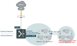
DMZ 1

As the previous description, DHCP relay agent enabled on a DMZ port forwards the DHCP messages between DMZ and a DHCP server. In FortiWAN, a DMZ can be deployed according the following WAN types:

l Routing Mode – IPv4 Basic Subnet: Subnet in DMZ l Routing Mode – IPv4 Basic Subnet: Subnet in WAN and DMZ l Bridge Mode – Multiple Static IP: IPv4 IP(s) in DMZ

No matter which WAN type a DMZ is deployed, it is necessary to configure the “IP(s) on Localhost” field to the DMZ port via Web UI. From the example above, we have configured the localhost of DMZ 1 port with three IP addresses 20.20.20.1 and 20.20.20.2. To enable DHCP Relay on this port, you need to check the check-box “Enable DHCP Relay” on the Web UI and configure the settings as follows:

DHCP Relay Server 1 10.10.10.10
DHCP Relay Agent IP 20.20.20.1 or 20.20.20.2

The DHCP server (10.10.10.10) recognizes the relay agent (the DMZ 1 port) that relayed the DHCP message through the “DHCP Relay Agent IP” contained in the relayed message. Then according to the DHCP addressing policy, it selects an IP belongs to subnet 20.20.20.x from its IP pool and responds to the relay agent on DMZ 1 port.

Note that the DHCP server working with FortiWAN’s DHCP Replay must be a standalone server.

FortiWAN’s DHCP function is not supported to work with DHCP Relay; a port with DHCP being enabled can not cooperate with the ports that DHCP Relay is enabled on. The centralized DHCP server working in a DHCP Relay deployment must be well-configured in the IP pools for the multiple IP subnets it is managing.

DHCP Relay over FortiWAN Tunnel Routing network

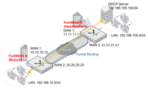
FortiWAN’s DHCP Relay is capable of forwarding DHCP messages through Tunnel Routing (See “Tunnel Routing”) so that the centralized IP addressing over a FortiWAN Tunnel Routing network can be implemented. This is useful for the application that a headquarters centrally manages IP allocation to its regional branches. The following shows the example that a DHCP server located in the headquarters site (deployed in the LAN subnet) manages the IP addressing to its branches through Internet.

With Tunnel Routing connectivity, a VPN network is established among networks of the two sites. DHCP relay in the VPN network serves for the subnets just as normal. FortiWAN A (the branch) delivers the relayed DHCP requests from its private subnet 192.168.10.0/24 to the DHCP server located in remote private subnet 192.168.100.0/24 over Internet; conversely, FortiWAN B (the headquarters) delivers the DHCP responses to the branch site over Internet and FortiWAN A will forward the response to its LAN to allocate a host the IP address. DHCP messages are delivered by Tunnel Routing encapsulation and decapsulation, just like normal Tunnel

Routing transmission. The localhost of LAN port on FortWAN A is configured to 192.168.10.254. Configuration of IP pool for subnet 192.168.10.0/24 is required on the DHCP server. The related configurations on the two FortiWAN units are as follows:

Configurations on FortiWAN A

Go to Network Setting > LAN Private Subnet > IPv4 Basic Subnetand select the subnet 192.168.10.0/24 to configure.

Check the checkbox Enable DHCP Relay and configure the setting below.

DHCP Relay Server 1 192.168.100.100
DHCP Relay Agent IP 192.168.10.254

Go to Service > Tunnel Routing and define a Tunnel Group with the two tunnels below:

Local IP Remote IP
10.10.10.10 11.11.11.11
20.20.20.20 21.21.21.21

Define the Routing Rule.

Source Destination Service Group
192.168.10.0/255.255.255.0 192.168.100.0/255.255.255.0 Any Group Name
Configurations on FortiWAN B

Go to Service > Tunnel Routing and define a Tunnel Group with the two tunnels below:

Local IP Remote IP
11.11.11.11 10.10.10.10
21.21.21.21 20.20.20.20

Define the Routing Rule.

Source Destination Service Group
192.168.100.0/255.255.255.0 192.168.10.0/255.255.255.0 Any Group Name

Note that the DHCP Relay can only work with Tunnel Routing or Tunnel Routing over IPSec Transport Mode. It does not support relaying DHCP requests through IPSec Tunnel Mode (See “IPSec VPN”).

IPv6 Automatic Addressing

FortiWAN provides stateless and stateful mechanisms to allocate IPv6 addresses to hosts in the following subnets or IP range:

DMZ Side l Routing Mode, IPv6 Basic Subnet: Subnet in DMZ
  l Routing Mode, IPv6 Basic Subnet: Subnet in WAN and DMZ
  l Bridge Mode: One Static IP, IPv6 Basic Subnet: Subnet in DMZ
  l Bridge Mode: Multiple Static IP, IPv6 IP(s) in DMZ
  l Bridge Mode: Multiple Static IP, IPv6 Basic Subnet: Subnet in DMZ
LAN Side l LAN Private Subnet

Stateless Address Autoconfiguration (SLAAC) is a standard mechanism to equip hosts with IPv6 addresses and related routing information through the IPv6 router advertisements (RA). SLAAC has two properties:

  • SLAAC is a stateless mechanism which is short of the IP management. SLAAC is incapable of controlling the

mapping between a host and an IPv6 address.

  • DNS information is absent from the traditional Router Advertisement messages. SLAAC with options of RDNSS and DNSSL included in RA messages (what is called SLAAC RDNSS) can convey information about DNS recursive servers and DNS Search Lists.

Comparing with SLAAC, DHCPv6 takes the advantage of IP management, so that is called stateful. By specifying the IP pool and static IP mapping, administrators are able to control how the IPv6 addresses be allocated via DHCPv6. FortiWAN provides both SLAAC RDNSS and DHCPv6 for the stateless and stateful IPv6 automatic addressing

Stateless IPv6 addressing: SLAAC

Enabling the stateless IPv6 addressing for the “IPv6 Basic Subnets” or “IPv6 (IPs) in DMZ” by checking the checkbox Enable SLAAC.

DNS Server   The recursive DNS servers used to serve the IPv6 subnet you are configuring (the Subnet field below). FortiWAN conveys it through router advertisement (RA) messages. Depending on the subnet type (DMZ-sided or LAN-sided), this could be the DNS server serving the global IPv6 subnets (public) that your ISP provides or the

DNS server for the unique local IPv6 subnet (private).

  l Single DNS server: the IPv6 addresses defined in System > Network

Setting > DNS Server > IPv6 Domain Name Server are listed here for your options

  l ALL: answer the hosts with all the defined IPv6 DNS servers information.
  l None: answer the hosts without containing any IPv6 DNS server information.

This option is only available for IPv6 LAN private subnet. For the DMZ-sided subnets (hosts in the subnets are supposed to be deployed with IPv6 global addresses), system behaves answering the hosts with all the defined DNZ servers information.

Subnet   The subnet deployed on the port (LAN port or DMZ port) you are configuring. SLAAC services the subnet. The subnet is used by SLAAC to allocate the prefix information to the hosts, so that an IPv6 address can be determined (with the Host ID) on a host. Depending on the subnet type, it could be a global IPv6 subnet or a unique local IPv6 subnet.
DNS Search List   A search list to be used when trying to resolve a name by means of the DNS. This option is only available for IPv6 LAN private subnet.

Stateful IPv6 addressing: DHCPv6

To enable the stateful IPv6 addressing for the “IPv6 Basic Subnets” or “IPv6 (IPs) in DMZ”, you are required to enable and configure both SLAAC and DHCPv6 on Web UI. FortiWAN will not respond for any Router

Advertisement (RA) if it SLAAC is disabled. The stateful IPv6 addressing via DHCPv6 requires RA to discover the default gateway for hosts, and therefor hosts fail to get default gateway if SLAAC is disabled. Please enable and configure the SLAAC as the introduction above if DHCPv6 is enable and make sure the network interface of a host is sat to automatically get the IPv6 address through DHCPv6.

FortiWAN acts a DHCPv6 server on the specified LAN port or DMZ port if checkbox Enable DHCPv6 Service is checked. All the hosts running as DHCPv6 client could gain the routing and DNS information from DHCPv6 server. DHCPv6 provides configuring and management to the IPv6 addresses to be assigned, which is a shortage of SLAAC.

DNS Server   The DNS DNS servers used to serve the IPv6 subnet you are configuring (the Subnet field below). FortiWAN responds to the DHCPv6 clients within the DHCPv6 messages if the clients are sat to automatically get DNS information through DHCPv6. Depending on the subnet type (DMZ-sided or LAN-sided), this could be the DNS server serving the global IPv6 subnets (public) that your ISP provides or the DNS server for the unique local IPv6 subnet

(private).

  l Single DNS server: the IPv6 addresses defined in System > Network Setting > DNS Server > IPv6 Domain Name Server are listed here for your options.
  l ALL: answer the hosts with all the defined IPv6 DNS servers information.
  l None: answer the hosts without containing any IPv6 DNS server information.

This option is only available for IPv6 LAN private subnet. For subnet in DMZ and subnet in WAN and DMZ (hosts in the subnets are supposed to be IPv6 global address deployment), system behaves answering the hosts with all the defined DNZ servers information.

DHCP Range   The address pools that DHCPv6 server assigns and manages IPv6 addresses from. Define the DHCP ranges by specifying IPv6 Starting Address and IPv6 Ending Address.
Static Mapping   DHCPv6 server assigns and manages IPv6 addresses according to client IDs. An IPv6 address that is mapped to a client ID is only available to this client. It will not be assigned to other clients even it is idle. Define the mapping by specifying Client ID and the correspondent IPv6 Address.
DNS Search List   A search list to be used when trying to resolve a name by means of the DNS. This option is only available for IPv6 LAN private subnet.

Note that IPv6 addresses defined in DHCP Range and Static Mapping must be also defined in filed IPv6 IP(s) in DMZ for a bridge-mode (multiple static IP) WAN link, the DMZ side of IPv6 basic subnets (subnet in WAN and DMZ, and subnet in DMZ) for a routing-mode WAN link and the IPv6 basic subnets of private LAN subnets.


Having trouble configuring your Fortinet hardware or have some questions you need answered? Check Out The Fortinet Guru Youtube Channel! Want someone else to deal with it for you? Get some consulting from Fortinet GURU!

[Static Routing Subnet]: Subnet in DMZ

 [Static Routing Subnet]: Subnet in DMZ

In this topology, in DMZ you create an IPv4 private subnet using one router (its IP, say, 192.168.34.50). But the subnet (its IP 192.168.99.0/24) does not connect to FortiWAN directly. Configure the subnet on FortiWAN to process its packets.


Having trouble configuring your Fortinet hardware or have some questions you need answered? Check Out The Fortinet Guru Youtube Channel! Want someone else to deal with it for you? Get some consulting from Fortinet GURU!

[Static Routing Subnet]: Subnet in WAN

 [Static Routing Subnet]: Subnet in WAN

This topology is found where IPv4 private static routing subnet is located on the WAN. In other words, the private subnet on the WAN does not connect to FortiWAN directly. Instead, it connects to a router which helps to transfer its packets.

Hence, in [Static Routing Subnet], [Gateway] IP address is that of the router.


Having trouble configuring your Fortinet hardware or have some questions you need answered? Check Out The Fortinet Guru Youtube Channel! Want someone else to deal with it for you? Get some consulting from Fortinet GURU!

FortiWAN WAN/DMZ Private Subnet

WAN/DMZ Private Subnet

After having gone through public subnet configurations, let’s move to private subnet settings. This section lists a few typical topology structures for private subnet. Similarly, FortiWAN supports two different types of private subnet according to the deployment, direct or indirect connecting to FortiWAN.The two settings are configured from [Basic Subnet] and [Static Routing Subnet]. FortiWAN supports both IPv4 and IPv6 for the two private subnet types.

On its UI, [IPv4 Basic Subnet] and [IPv6 Basic Subnet] could be one of:

  • Subnet in WAN l Subnet in DMZ l Subnet in WAN and DMZ
  • Subnet on Localhost (Not support in [IPv6 Basci Subnet])

And [IPv4 Static Routing Subnet] and [IPv6 Static Routing Subnet] could be one of:

  • Subnet in WAN l Subnet in DMZ

[Basic Subnet]: Subnet in WAN

This topology is frequently found where cluster hosts in the IPv4 private subnet are located on the WAN. In this example, FortiWAN port2 has been mapped to WAN port, with IP 192.168.3.1. Select [Subnet in WAN] from [Subnet Type] in [Basic Subnet]. Then enter 192.168.3.1 in [IP(s) on Localhost] and the netmask offered by ISP in [Netmask].

Note: FortiWAN assumes that IP addresses that are unlisted in [IP(s) on Localhost] are all in WAN.

[Basic Subnet]: Subnet in DMZ

This topology is frequently found where cluster hosts in IPv4 private subnet are located on the DMZ. In this example, FortiWAN port5 has been mapped to DMZ port, with private IP 192.168.4.254. And subnet 192.168.4.X is located on the DMZ as a whole. From UI, select [Subnet in DMZ] from [Subnet Type] in [Basic Subnet].

Check [Enable DHCP] if hosts in the subnet in DMZ require DHCP service. And enter the starting and ending address in [DHCP Range]. If any host in the subnet uses static IP address, then in [Static Mapping], enter its IP and MAC address. Note: FortiWAN assumes IP addresses that are unlisted in [IP(s) on Localhost] are all in DMZ. Thus there is no need to configure them.

[Basic Subnet]: Subnet in WAN and DMZ

This topology is found where cluster hosts in IPv4 private subnet are located in both WAN and DMZ. FortiWAN hereby assumes IP addresses that are unlisted in [IP(s) on Localhost] and [IP(s) in WAN] are all in the DMZ. Port2 and port5 are connected in dotted line, indicating the subnet spreads across WAN (port2) and DMZ (port5). FortiWAN employs Proxy ARP to connet the whole subnet togther. In this example, more than one IP addresses are needed for FortiWAN in bridging. These IP addresses therefore have to be on the same network segment.

Enter 192.168.5.20-192.168.5.30 in [IP(s) on Localhost], and 192.168.5.10-192.168.5.19 in [IP(s) in WAN].

[Basic Subnet]: Subnet on Localhost

This topology is found where a whole IPv4 private subnet is designated on FortiWAN. And the IP addresses in this subnet can be utilized by Virtual Server. An IPv6 private subnet is not supported for this subnet type.


Having trouble configuring your Fortinet hardware or have some questions you need answered? Check Out The Fortinet Guru Youtube Channel! Want someone else to deal with it for you? Get some consulting from Fortinet GURU!

LAN Private Subnet

LAN Private Subnet

[LAN Private Subnet] is the second most important part for deploying FortiWAN in your network. In contrast with configurations on WAN Settings to active the WAN link transmission from FortiWAN to Internet (external network), LAN Private Subnet is the configuration for deploying the internal network on FortiWAN’s LAN ports. There are two parts for setting LAN private subnet: Basic Subnet and Static Routing Subnet, which respectively are the subnets connected directly to FortiWAN’s LAN ports and the subnets connected indirectly to FortiWAN via a router. (See “Scenarios to deploy subnets”)

Basic Subnet

Here is a simple example to demonstrate a configuration for the basic subnet in the typical LAN environment.

As the illustration, FortiWAN port3 has been mapped to LAN port via [System / Network Setting / VLAN and Port Mapping] (See “VLAN and Port Mapping”), and is assigned with private IP 192.168.34.254. Enter this IP address in the field [IP(s) on Localhost]. For hosts in LAN, port3 (192.168.34.254) serves as gateway as well. Enter the netmask (255.255.255.0) for the subnet in the field [Netmask]. Select the LAN port.

IPv4 Basic Subnet  
IP(s) on Localhost 192.168.34.254
Netmask 255.255.255.0
LAN Port Port3

Check the field in [Enable DHCP], to allocate IP address (any of 192.168.34.175~192.168.34.199) dynamically via DHCP to PCs in LAN. If any host in LAN requires static IP addresses, then enter in [Static Mapping] the IP addresses to designate, and MAC addresses of the PCs as well. Check the field in [NAT Subnet for VS], which is an optional choice. When users in LAN or DMZ access the WAN IP of virtual server, their packets may bypass FortiWAN and flow to internal server directly. This function can translate the source IP address of the users’ packets into IP address of FortiWAN, to ensure the packets flow through FortiWAN. If no check is made, the system will determine which IP address it may translate into by itself. Similarly, to deploy an IPv6 private LAN on FortiWAN port4 which has been mapped to LAN port, with IPv6 address 2001:a:b:cd08::1 served as gateway for PCs in LAN. Check the field in [Enable SLAAC] or [Enable DHCPv6 Service] to allocate IP addresses dynamically to PCs in LAN. [NAT Subnet for VS] is not supported in IPv6 private LAN. The SLAAC and DHCPv6 in FortiWAN are designed to work together, which the SLAAC responses router advertisement (including default gateway and DNS server) to a host and DHCPv6 responses the host an appropriate IPv6 address.

For the details about DHCP, DHCP Relay, SLAAC and DHCPv6, see “Automatic addressing within a basic subnet”.

Static Routing Subnet

[Static Routing Subnet] is useful when in LAN a router .is used to cut out a separate subnet which does not connect to FortiWAN directly. The topology is similar to [Static Routing Subnet: Subnet in DMZ] mentioned previously, and the only difference is this example is set in LAN rather than in DMZ. In this topology below, a subnet 192.168.99.x is located in the LAN and connects to router 192.168.34.50, while another subnet 192.168.34.x is located on the LAN port as well, but connects to FortiWAN directly. The configurations here indicate how FortiWAN to route packets to subnet 192.168.99.x.

IPv4 Static Routing Subnet  
Network IP 192.168.99.0
Netmask 255.255.255.0
Gateway 192.168.34.50

RIP

FortiWAN supports the Routing Information Protocol (RIP v1, v2), RIP employs hot count as the metric, and uses timer broadcast to update the router. As RIP features configuration simplicity and operation convenience, it has been widely used across all fields. RIP version 1 (v1)1 was designed to suit the dynamic routing needs of LAN technology-based IP internetworks, and to address some problems associated with RIP v1, a refined RIP, RIP version 2 (v2) was defined. RIP v2 supports sending RIP announcements to the IP multicast address and supports the use of authentication mechanisms to verify the origin of incoming RIP announcements.

Check the field in [RIP] if you have enabled RIP on your private subnet router. Check the field in [RIP v1] if you have enabled RIP v1 on your private subnet router behind FortiWAN. Thus, FortiWAN can forward packets from the RIP v1-enabled private subnet. Otherwise, check the field in [RIP v2] if you have enabled RIP v2 on your private subnet router. Thus, FortiWAN can forward RIP v2 packets. Moreover, if you have enabled RIP v2 authentication, type the password in [Password]. Otherwise, keep [Password] blank.

OSPF

Apart from RIP, FortiWAN also supports OSPF (Open Shortest Path First), to assign LAN port router with given preference. Like RIP, OSPF is designated by the Internet Engineering Task Force (IETF) as one of several Interior Gateway Protocols (IGPs). Rather than simply counting the number of hops, OSPF bases its path descriptions on “link states” that take into account additional network information. Using OSPF, a host that obtains a change to a routing table or detects a change in the network immediately multicasts the information to all other hosts in the network so that all will have the same routing table information.

OSPF Interface Displays the LAN port in the network. Check the box to enable OSPF over the port.
Area Setting Network is logically divided into a number of areas based on subnets.

Administrators can configure area ID, which accepts numbers or IPs only.

Authentication Setting Routers in different areas require authentication to communicate with each other. Authentication types: Null, Simple Text Password, MD5.
Router Priority Set router priority. Router that sends the highest OSPF priority becomes DR (Designated Router). The value of the OSPF Router Priority can be a number between 0 and 255.
Hello Interval Set the interval, in seconds, to instruct the router to send out OSPF keepalive packets to inform the other routers.
Dead Interval Set the length of time, in seconds, that OSPF neighbors will wait without receiving an OSPF keepalive packet from a neighbor before declaring the neighbor router is down.
Retransmit Interval Set the interval, in seconds, between retransmissions of Link ups. When routers fail to transmit hello packets, it will retransmit packets in the defined interval.
Authentication Type This specifies whether the router will perform authentication of data passing the LAN. Choices are: Null, Simple Text Password, MD5.

FortiWAN provides statistics for the RIP & OSPF service, see “RIP & OSPF Status”.

VRRP

VRRP is a Virtual Router Redundancy Protocol that runs on a LAN port. A system can switch between VRRP or HA mode; when switched, the system will reboot first for changes to take effect. When VRRP mode is enabled, the HA mode will be automatically disabled, and also a VRID field will appear available for input in [VLAN and Port Mapping] setting page (See “VLAN and Port Mapping”). In general, VRRP is faster in detecting the master unit compared to HA mode. Although FortiWAN’s VRRP implementation is based on VRRP version 3, some restrictions may apply:

  • Always in non-preempt mode. l Always in non-accept mode.
  • IPv6 is not supported. l Active-active mode is not supported.

When FortiWAN switches to master mode, it automatically starts WAN link health detection. When it switches to backup mode, it automatically stops WAN link health detection and sets WAN status to “failed”.

In addition, DHCP servers in LAN and DMZ should let clients use FortiWAN virtual IP and the default gateway (as FortiWAN’s DHCP service does). If RIP and OSPF is used in LAN, FortiWAN uses real IP at OSPF and virtual IP at RIP to exchange route information. Clone-MAC settings will be ignored if VRRP function is enabled. FortiWAN doesn’t exchange NAT table with VRRP peers. When VRRP master changes, existing connection might break.

Local Priority The priority field specifies the sending VRRP router’s priority for the virtual router. Select a number from 1 to 254 as the priority for the VR.
Advertisement Interval Set the time interval in centi-seconds between advertisements. (Default is 100)
Virtual address Enter a virtual IP address for the virtual router.
Double-check Link Click the checkbox to enable. When enabled, the backup router will check whether the master is responding ARP on the specified WAN port.
See also
  • Scenarios to deploy subnets
  • VLAN and Port Mapping
  • Summary
  • RIP & OSPF Status

Having trouble configuring your Fortinet hardware or have some questions you need answered? Check Out The Fortinet Guru Youtube Channel! Want someone else to deal with it for you? Get some consulting from Fortinet GURU!