Tag Archives: fortigate wan optimization

WAN optimization, web caching and memory usage

WAN optimization, web caching and memory usage

To accelerate and optimize disk access and to provide better throughput and less latency FortiOS WAN optimization uses provisioned memory to reduce disk I/O and increase disk I/O efficiency. In addition, WAN optimization requires a small amount of additional memory per session for comprehensive flow control logic and efficient traffic forwarding.

When WAN optimization is enabled you will see a reduction in available memory. The reduction increases when more WAN optimization sessions are being processed. If you are thinking of enabling WAN optimization on an operating FortiGate unit, make sure its memory usage is not maxed out during high traffic periods.

In addition to using the system dashboard to see the current memory usage you can use the get test wad 2 command to see how much memory is currently being used by WAN optimization. See “get test {wad | wccpd} <test_level>” for more information.


Having trouble configuring your Fortinet hardware or have some questions you need answered? Check Out The Fortinet Guru Youtube Channel! Want someone else to deal with it for you? Get some consulting from Fortinet GURU!

Configuring WAN optimization

Configuring WAN optimization

This chapter describes FortiGate WAN optimization client server architecture and other concepts you need to understand to be able to configure FortiGate WAN optimization.


Client/server architecture

Traffic across a WAN typically consists of clients on a client network communicating across a WAN with a remote server network. The clients do this by starting communication sessions from the client network to the server network. These communication sessions can be open text over the WAN or they can be encrypted by SSL VPN or IPsec VPN.

To optimize these sessions, you can add WAN optimization security policies to the client-side FortiGate unit to accept sessions from the client network that are destined for the server network. The client-side FortiGate unit is located between the client network and the WAN. WAN optimization security policies include WAN optimization profiles that control how the traffic is optimized.

The client-side FortiGate unit must also include the IP address of the server-side FortiGate unit in its WAN optimization peer configuration. The server-side FortiGate unit is located between the server network and the WAN, The peer configuration allows the client-side FortiGate unit to find the server-side FortiGate unit and attempt to establish a WAN optimization tunnel with it.

For the server-side FortiGate unit you must add a security policy with wanopt as the Incoming Interface. This security policy allows the FortiGate unit to accept WAN optimization sessions from the client-side FortiGate unit. For the server-side FortiGate unit to accept a WAN optimization connection it must have the client-side FortiGate unit in its WAN optimization peer configuration.

WAN optimization profiles are only added to the client-side WAN optimization security policy. The server-side FortiGate unit employs the WAN optimization settings set in the WAN optimization profile on the client-side FortiGate unit.


Client/server architecture

When both peers are identified the FortiGate units attempt to establish a WAN optimization tunnel between them. WAN optimization tunnels use port 7810. All optimized data flowing across the WAN between the client- side and server-side FortiGate units use this tunnel. WAN optimization tunnels can be encrypted use SSL encryption to keep the data in the tunnel secure.

Any traffic can be sent through a WAN optimization tunnel. This includes SSL and IPsec VPN traffic. However, instead of configuring SSL or IPsec VPN for this communication you can add SSL encryption using the WAN optimization tunnel.

In addition to basic identification by peer host ID and IP address you can configure WAN optimization authentication using certificates and pre-shared keys to improve security. You can also configure FortiGate units involved in WAN optimization to accept connections from any identified peer or restrict connections to specific peers.

The FortiClient application can act in the same manner as a client-side FortiGate unit to optimize traffic between a computer running FortiClient and a FortiGate unit.


Having trouble configuring your Fortinet hardware or have some questions you need answered? Check Out The Fortinet Guru Youtube Channel! Want someone else to deal with it for you? Get some consulting from Fortinet GURU!

WAN optimization and HA

WAN optimization and HA

You can configure WAN optimization on a FortiGate HA cluster. The recommended HA configuration for WAN optimization is active-passive mode. Also, when the cluster is operating, all WAN optimization sessions are processed by the primary unit only. Even if the cluster is operating in active-active mode, HA does not load- balance WAN optimization sessions. HA also does not support WAN optimization session failover.

In a cluster, the primary unit only stores web cache and byte cache databases. These databases are not synchronized to the subordinate units. So, after a failover, the new primary unit must rebuild its web and byte caches. As well, the new primary unit cannot connect to a SAS partition that the failed primary unit used.

Rebuilding the byte caches can happen relatively quickly because the new primary unit gets byte cache data from the other FortiGate units that it is participating with in WAN optimization tunnels.


Failover and attached network equipment

It normally takes a cluster approximately 6 seconds to complete a failover. However, the actual failover time experienced by your network users may depend on how quickly the switches connected to the cluster interfaces accept the cluster MAC address update from the primary unit. If the switches do not recognize and accept the gratuitous ARP packets and update their MAC forwarding table, the failover time will increase.

Also, individual session failover depends on whether the cluster is operating in active-active or active-passive mode, and whether the content of the traffic is to be virus scanned. Depending on application behavior, it may take a TCP session a longer period of time (up to 30 seconds) to recover completely.


Monitoring cluster units for failover

You can use logging and SNMP to monitor cluster units for failover. Both the primary and subordinate units can be configured to write log messages and send SNMP traps if a failover occurs. You can also log into the cluster web-based manager and CLI to determine if a failover has occurred.


NAT/Route mode active-passive cluster packet flow

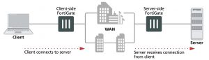
This section describes how packets are processed and how failover occurs in an active-passive HA cluster running in NAT/Route mode. In the example, the NAT/Route mode cluster acts as the internet firewall for a client computer’s internal network. The client computer’s default route points at the IP address of the cluster internal interface. The client connects to a web server on the Internet. Internet routing routes packets from the cluster external interface to the web server, and from the web server to the cluster external interface.

In an active-passive cluster operating in NAT/Route mode, four MAC addresses are involved in communication between the client and the web server when the primary unit processes the connection:

  • Internal virtual MAC address (MAC_V_int) assigned to the primary unit internal interface,
  • External virtual MAC address (MAC_V_ext) assigned to the primary unit external interface,
  • Client MAC address (MAC_Client),
  • Server MAC address (MAC_Server),

In NAT/Route mode, the HA cluster works as a gateway when it responds to ARP requests. Therefore, the client and server only know the gateway MAC addresses. The client only knows the cluster internal virtual MAC address (MAC_V_int) and the server only know the cluster external virtual MAC address (MAC_V_int).


NAT/Route mode active-passive packet flow


Packet flow from client to web server

1. The client computer requests a connection from 10.11.101.10 to 172.20.120.130.

2. The default route on the client computer recognizes 10.11.101.100 (the cluster IP address) as the gateway to the external network where the web server is located.

3. The client computer issues an ARP request to 10.11.101.100.

4. The primary unit intercepts the ARP request, and responds with the internal virtual MAC address (MAC_V_int) which corresponds to its IP address of 10.11.101.100.

5. The client’s request packet reaches the primary unit internal interface.


  IP address MAC address
Source 10.11.101.10 MAC_Client
Destination 172.20.120.130 MAC_V_int


6. The primary unit processes the packet.

7. The primary unit forwards the packet from its external interface to the web server.


  IP address MAC address
Source 172.20.120.141 MAC_V_ext
Destination 172.20.120.130 MAC_Server


8. The primary unit continues to process packets in this way unless a failover occurs.


Packet flow from web server to client

1. When the web server responds to the client’s packet, the cluster external interface IP address (172.20.120.141) is recognized as the gateway to the internal network.

2. The web server issues an ARP request to 172.20.120.141.

3. The primary unit intercepts the ARP request, and responds with the external virtual MAC address (MAC_V_ext) which corresponds its IP address of 172.20.120.141.

4. The web server then sends response packets to the primary unit external interface.


  IP address MAC address
Source 172.20.120.130 MAC_Server
Destination 172.20.120.141 MAC_V_ext


5. The primary unit processes the packet.

6. The primary unit forwards the packet from its internal interface to the client.


  IP address MAC address
Source 172.20.120.130 MAC_V_int
Destination 10.11.101.10 MAC_Client


7. The primary unit continues to process packets in this way unless a failover occurs.


When a failover occurs

The following steps are followed after a device or link failure of the primary unit causes a failover.

1. If the primary unit fails the subordinate unit becomes the primary unit.

2. The new primary unit changes the MAC addresses of all of its interfaces to the HA virtual MAC addresses.

The new primary unit has the same IP addresses and MAC addresses as the failed primary unit.

3. The new primary units sends gratuitous ARP packets from the internal interface to the 10.11.101.0 network to associate its internal IP address with the internal virtual MAC address.

4. The new primary units sends gratuitous ARP packets to the 172.20.120.0 to associate its external IP address with the external virtual MAC address.

5. Traffic sent to the cluster is now received and processed by the new primary unit.

If there were more than two cluster units in the original cluster, these remaining units would become subordinate units.


Having trouble configuring your Fortinet hardware or have some questions you need answered? Check Out The Fortinet Guru Youtube Channel! Want someone else to deal with it for you? Get some consulting from Fortinet GURU!

WAN Optimization

WAN Optimization

WAN Optimization features require significant memory resources and generate a high amount of I/O on disk. Before enabling WAN Optimization, ensure that the memory usage is not too high. If possible, avoid other disk- intensive features such as heavy traffic logging on the same disk as the one configured for WAN Optimization needs.

In general, it is preferable to enable the Transparent Mode checkbox and ensure that routing between the two endpoints is acceptable. Some protocols may not work well without enabling Transparent Mode.

Other best practices for utilizing the WAN Optimization feature follow.


Sharing the WAN Opt. tunnel for traffic of the same nature

WAN optimization tunnel sharing is recommended for similar types of WAN optimization traffic (such as CIFS traffic from different servers). However, tunnel sharing for different types of traffic is not recommended. For example, aggressive and non-aggressive protocols should not share the same tunnel.


Ordering WAN Opt. rules appropriately

  • Precise, port specific WAN Optimization rules should be at the top of the list.
  • Generic rules, such as overall TCP, should be at the bottom of the list.


Avoiding mixing protocols in a WAN Opt. tunnel

Different protocols may be more or less talkative or interactive . Mixing protocols in a tunnel may result in a delay for some of them. It is recommended to define protocol specific wan-optimization rules and restrict the ports to the necessary ones only for performance reasons.


Setting correct configuration options for CIFS WAN Opt.

Ensure that the WAN Optimization rules cover TCP ports 139 and 445 (on the same or two different rules). Also ensure that Transparent Mode is selected.


Setting correct configuration options for MAPI WAN Opt.

For MAPI WAN Optimization, only specify a rule with TCP port 135 (unless the MAPI control port is configured differently). Derived data sessions using other random ports will be handled by the CIFS wan-optimization daemon even with only the control port configured.


Testing WAN Opt. in a lab

  • Ensure that WAN emulators are used to simulate the WAN. If no WAN emulator is used, it is expected to have better results without WAN Optimization than with WAN Optimization.
  • To test the difference between cold transfers (first-time transfers) and warm transfers, it is recommended to generate a random file of the cold transfer to ensure that the test is the first time that the file has been seen.


Regarding byte compression and type of file

Enabling byte compression on file transfers already compressed (.jpeg files, compressed archive, etc.) won’t provide any performance increase and could be seen as a misuse of CPU resources.


Regarding network address translation (NAT)

Selecting the NAT feature in a security policy does not have any influence on WAN Optimization traffic.


High Availability

There is no benefit to using active-active mode, so for pure WAN Optimization needs, use active-passive mode. Refer to the FGCP High Availability section for other best practices related to HA.


Authentication with specific peers

Configure WAN optimization authentication with specific peers. Accepting any peer is not recommended as this can be less secure.


Having trouble configuring your Fortinet hardware or have some questions you need answered? Check Out The Fortinet Guru Youtube Channel! Want someone else to deal with it for you? Get some consulting from Fortinet GURU!