FortiClient dialup-client configurations

FortiClient dialup-client configurations

The FortiClient Endpoint Security application is an IPsec VPN client with antivirus, antispam and firewall capabilities. This section explains how to configure dialup VPN connections between a FortiGate unit and one or more FortiClient Endpoint Security applications.

FortiClient users are usually mobile or remote users who need to connect to a private network behind a FortiGate unit. For example, the users might be employees who connect to the office network while traveling or from their homes.

For greatest ease of use, the FortiClient application can download the VPN settings from the FortiGate unit to configure itself automatically.

The following topics are included in this section: Configuration overview

  • FortiClient-to-FortiGate VPN configuration steps
  • Configure the FortiGate unit
  • Configure the FortiClient Endpoint Security application
  • Adding XAuth authentication
  • FortiClient dialup-client configuration example


Configuration overview

Dialup users typically obtain dynamic IP addresses from an ISP through Dynamic Host Configuration Protocol (DHCP) or Point-to-Point Protocol over Ethernet (PPPoE). Then, the FortiClient Endpoint Security application initiates a connection to a FortiGate dialup server.

By default the FortiClient dialup client has the same IP address as the host PC on which it runs. If the host connects directly to the Internet, this is a public IP address. If the host is behind a NAT device, such as a router, the IP address is a private IP address. The NAT device must be NAT traversal (NAT-T) compatible to pass encrypted packets (see Phase 1 parameters on page 1624). The FortiClient application also can be configured to use a virtual IP address (VIP). For the duration of the connection, the FortiClient application and the FortiGate unit both use the VIP address as the IP address of the FortiClient dialup client.

The FortiClient application sends its encrypted packets to the VPN remote gateway, which is usually the public interface of the FortiGate unit. It also uses this interface to download VPN settings from the FortiGate unit. See Automatic configuration of FortiClient dialup clients on page 1703.


Example FortiClient dialup-client configuration

forticlient-dialup-client

Peer identification

The FortiClient application can establish an IPsec tunnel with a FortiGate unit configured to act as a dialup server. When the FortiGate unit acts as a dialup server, it does not identify the client using the Phase 1 remote gateway address. The IPsec tunnel is established if authentication is successful and the IPsec security policy associated with the tunnel permits access. If configured, the FortiGate unit could also require FortiClient registration, that is, the remote user would be required to have FortiClient installed before connection is completed.


Automatic configuration of FortiClient dialup clients

The FortiClient application can obtain its VPN settings from the FortiGate VPN server. FortiClient users need to know only the FortiGate VPN server IP address and their user name and password on the FortiGate unit.


The FortiGate unit listens for VPN policy requests from clients on TCP port 8900. When the dialup client connects:

  • The client initiates a Secure Sockets Layer (SSL) connection to the FortiGate unit.
  • The FortiGate unit requests a user name and password from the FortiClient user. Using these credentials, it authenticates the client and determines which VPN policy applies to the client.
  • Provided that authentication is successful, the FortiGate unit downloads a VPN policy to the client over the SSL connection. The information includes IPsec Phase 1 and Phase 2 settings, and the IP addresses of the private networks that the client is authorized to access.
  • The client uses the VPN policy settings to establish an IPsec Phase 1 connection and Phase 2 tunnel with the FortiGate unit.

Having trouble configuring your Fortinet hardware or have some questions you need answered? Check Out The Fortinet Guru Youtube Channel! Want someone else to deal with it for you? Get some consulting from Fortinet GURU!

Dynamic DNS configuration

Dynamic DNS configuration

This section describes how to configure a site-to-site VPN, in which one FortiGate unit has a static IP address and the other FortiGate unit has a domain name and a dynamic IP address.

  • The following topics are included in this section: Dynamic DNS over VPN concepts
  • Dynamic DNS topology
  • General configuration steps
  • Configure the dynamically-addressed VPN peer
  • Configure the fixed-address VPN peer
  • Testing


Dynamic DNS over VPN concepts

A typical computer has a static IP address and one or more DNS servers to resolve fully qualified domain names (FQDN) into IP addresses. A domain name assigned to this computer is resolved by any DNS server having an entry for the domain name and its static IP address. The IP address never changes or changes only rarely so the DNS server can reliably say it has the correct address for that domain all the time.


Dynamic DNS (DDNS)

It is different when a computer has a dynamic IP address, such as an IP address assigned dynamically by a DHCP server, and a domain name. Computers that want to contact this computer do not know what its current IP address is. To solve this problem there are dynamic DNS servers. These are public servers that store a DNS entry for your computer that includes its current IP address and associated domain name. These entries are kept up to date by your computer sending its current IP address to the dynamic DNS (DDNS) server to ensure its entry is always up to date. When other computers want to contact your domain, their DNS gets your IP address from your DDNS server. To use DDNS servers, you must subscribe to them and usually pay for their services.

When configuring DDNS on your FortiGate unit, go to Network > DNS and enable Enable FortiGuard DDNS. Then select the interface with the dynamic connection, which DDNS server you have an account with, your domain name, and account information. If your DDNS server is not on the list, there is a generic option where you can provide your DDNS server information.


Routing

When an interface has some form of changing IP address (DDNS, PPPoE, or DHCP assigned address), routing needs special attention. The standard static route cannot handle the changing IP address. The solution is to use the dynamic-gateway command in the CLI. Say for example you already have four static routes, and you have a PPPoE connection over the wan2 interface and you want to use that as your default route.

The route is configured on the dynamic address VPN peer trying to access the static address FortiGate unit.


To configure dynamic gateway routing – CLI

config router static edit 5

set dst 0.0.0.0 0.0.0.0

set dynamic-gateway enable set device wan2

next end


For more information on DDNS, see the System Administration handbook chapter.


Dynamic DNS over VPN

IPsec VPN expects an IP address for each end of the VPN tunnel. All configuration and communication with that tunnel depends on the IP addresses as reference points. However, when the interface the tunnel is on has DDNS enabled there is no set IP address. The remote end of the VPN tunnel now needs another way to reference your end of the VPN tunnel. This is accomplished using Local ID.

A FortiGate unit that has a domain name and a dynamic IP address can initiate VPN connections anytime. The remote peer can reply to the local FortiGate unit using the source IP address that was sent in the packet header because it is current. Without doing a DNS lookup first, the remote peer runs the risk of the dynamic IP changing before it attempts to connect. To avoid this, the remote peer must perform a DNS lookup for the domain name of to be sure of the dynamic IP address before initiating the connection.


Remote Gateway

When configuring the Phase 1 entry for a VPN tunnel, the Remote Gateway determines the addressing method the remote end of the tunnel uses as one of Static IP Address, Dialup User, or Dynamic DNS. There are different fields for each option.

When you select the Dynamic DNS VPN type there is a related field called Dynamic DNS. The Dynamic DNS field is asking for the FQDN of the remote end of the tunnel. It uses this information to look up the IP address of the remote end of the tunnel through the DDNS server associated with that domain name.


Local ID (peer ID)

The Local ID or peer ID can be used to uniquely identify one end of a VPN tunnel. This enables a more secure connection. Also if you have multiple VPN tunnels negotiating, this ensures the proper remote and local ends connect. When you configure it on your end, it is your Local ID. When the remote end connects to you, they see it as your peer ID.

If you are debugging a VPN connection, the Local ID is part of the VPN negotiations. You can use it to help troubleshoot connection problems.


To configure your Local ID

1. Go to VPN > IPsec Tunnels and create the new custom tunnel or edit an existing tunnel.

2. Edit the Phase 1 Proposal (if it is not available, you may need to click the Convert to Custom Tunnel button).

3. Select Advanced.

4. In the Phase 1 Proposal section, enter your Local ID.

5. Select OK.

The default configuration is to accept all local IDs (peer IDs). If you have the Local ID set, the remote end of the tunnel must be configured to accept your Local ID.


To accept a specific Peer ID

1. Go to VPN > IPsec Tunnels and create the new custom tunnel or edit an existing tunnel.

2. Edit the Phase 1 Proposal (if it is not available, you may need to click the Convert to Custom Tunnel button).

3. Select Aggressive mode.

4. For Peer Options, select This peer ID. This option becomes visible only when Aggressive mode is selected.

5. Enter the string the other end of the tunnel used for its Local ID.

6. Configure the rest of the Phase 1 entry as required.

7. Select OK.


Routebased or policy-based VPN

VPN over dynamic DNS can be configured with either route-based or policy-based VPN settings. Both are valid, but have differences in configuration. Choose the best method based on your requirements. For more information on route-based and policy-based, see IPsec VPN overview on page 1606.

Route-based VPN configuration requires two security policies to be configured (one for each direction of traffic) to permit traffic over the VPN virtual interface, and you must also add a static route entry for that VPN interface or the VPN traffic will not reach its destination. See Dynamic DNS over VPN concepts on page 1688 and Dynamic DNS over VPN concepts on page 1688.

Policy-based VPN configuration uses more complex and often more IPsec security policies, but does not require a static route entry. It has the benefit of being able to configure multiple policies for handling multiple protocols in different ways, such as more scanning of less secure protocols or guaranteeing a minimum bandwidth for protocols such as VoIP. See Dynamic DNS over VPN concepts on page 1688 and Dynamic DNS over VPN concepts on page 1688.


Dynamic DNS topology

In this scenario, two branch offices each have a FortiGate unit and are connected in a gateway-to-gateway VPN configuration. One FortiGate unit has a domain name (example.com) with a dynamic IP address. See branch_2 in the figure below.

Whenever the branch_2 unit connects to the Internet (and possibly also at predefined intervals set by the ISP), the ISP may assign a different IP address to the FortiGate unit. The unit has its domain name registered with a dynamic DNS service. The branch_2 unit checks in with the DDNS server on a regular basis, and that server provides the DNS information for the domain name, updating the IP address from time to time. Remote peers have to locate the branch_2 FortiGate unit through a DNS lookup each time to ensure the address they get is current and correct.


Example dynamic DNS configuration

dynamic-dns-configuration

When a remote peer (such as the branch_1 FortiGate unit above) initiates a connection to example.com, the local DNS server looks up and returns the IP address that matches the domain name example.com. The remote peer uses the retrieved IP address to establish a VPN connection with the branch_2 FortiGate unit.


Assumptions

  • You have administrator access to both FortiGate units.
  • Both FortiGate units have interfaces named wan1 and internal. (If not, you can use the alias feature to assign these labels as “nicknames” to other interfaces to follow this example.)
  • Both FortiGate units have the most recent firmware installed, have been configured for their networks, and are currently passing normal network traffic.
  • The branch_2 FortiGate unit has its wan1 interface defined as a dynamic DNS interface with the domain name of example.com.
  • A basic gateway-to-gateway configuration is in place (see Gateway-to-gateway configurations on page 1655) except one of the FortiGate units has a static domain name and a dynamic IP address instead of a static IP address.
  • The FortiGate unit with the domain name is subscribed to one of the supported dynamic DNS services. Contact one of the services to set up an account. For more information and instructions about how to configure the FortiGate unit to push its dynamic IP address to a dynamic DNS server, see the System Administration handbook chapter.


General configuration steps

When a FortiGate unit receives a connection request from a remote VPN peer, it uses IPsec Phase 1 parameters to establish a secure connection and authenticate the VPN peer. Then, if the security policy permits the connection, the FortiGate unit establishes the tunnel using IPsec Phase 2 parameters and applies the security policy. Key management, authentication, and security services are negotiated dynamically through the IKE protocol.


To support these functions, the following general configuration steps must be performed:

  • Configure the branch_2 FortiGate unit with the dynamic IP address. This unit uses a Local ID string instead of an IP address to identify itself to the remote peer. See General configuration steps below.
  • General configuration steps
  • General configuration steps
  • Configure the fixed-address VPN peer. To initiate a VPN tunnel with the dynamically-addressed peer, this unit must first retrieve the IP address for the domain from the dynamic DNS service. See General configuration steps on page 1691.
  • General configuration steps
  • General configuration steps


Configure the dynamically-addressed VPN peer

It is assumed that this FortiGate unit (branch_2) has already had its public facing interface, for example the wan1, configured with the proper dynamic DNS configuration.


Configure branch_2, the dynamic address side

dynamic-address-side

Configuring the dynamically-addressed VPN peer includes:

  • Configuring branch_2 VPN tunnel settings
  • Configuring branch_2 security policies


Configuring branch_2 VPN tunnel settings

Define the Phase 1 parameters needed to establish a secure connection with the remote peer. See Phase 1 parameters on page 1624. During this procedure you need to choose if you will be using route-based or policy- based VPNs.


To configure branch_2 VPN tunnel settings

1. Go to VPN > IPsec Tunnels and create the new custom tunnel or edit an existing tunnel.

2. Edit the Phase 1 Proposal (if it is not available, you may need to click the Convert to Custom Tunnel button).

3. Enter the following information:

Name                                           Enter branch_2, a name to identify the VPN tunnel. This name appears in Phase 2 configurations, security policies, and the VPN monitor.

Remote Gateway                               Select Static IP Address.

The remote peer this FortiGate is connecting to has a static IP public address.

If the remote interface is PPPoE do not select Retrieve default gateway from server.

IP Address                                 Enter 172.16.20.1. The IP address of the public interface to the remote peer.

Enter 172.16.20.1

The IP address of the public interface to the remote peer.

Select Aggressive.

4. Select Advanced and complete the following:

Local ID                                              Enter example.com.

A character string used by the branch_2 FortiGate unit to identify itself to the remote peer.

This value must be identical to the value in the This peer ID field of the Phase 1 remote gateway configuration on the branch_1 remote peer. See Configure the dynamically- addressed VPN peer on page 1692.

5. Open the Phase 2 Selectors panel.

Define the Phase 2 parameters needed to create a VPN tunnel with the remote peer. For details on Phase 2, see

Phase 2 parameters on page 1642.

6. Enter the following information and select OK.

Name                                                  Enter branch_2_phase2.

A name to identify this Phase 2 configuration.

Phase 1                                              Select branch_2.

The name of the Phase 1 configuration that you defined earlier.


Configuring branch_2 security policies

Define security policies to permit communications between the private networks through the VPN tunnel. Route- based and policy-based VPNs require different security policies. For detailed information about creating security policies, see Defining VPN security policies on page 1648.

After defining the two address ranges, select one of Creating branch_2 route-based security policies on page 1694 or Creating branch_2 policy-based security policies on page 1696 to configure the appropriate VPN policies.


Define address ranges for branch_2 security policies

Define VPN connection names for the address ranges of the private networks. These addresses are used in the security policies that permit communication between the networks. For more information, see Defining VPN security policies on page 1648.

Define an address name for the IP address and netmask of the private network behind the local FortiGate unit.


To define branch_2 address ranges

1. Go to Policy & Objects > Addresses.

2. Select Create New.

3. Enter the following information, and select OK.

Name                                          Enter branch_2_internal. Enter a meaningful name.

Type                                            Select Subnet.

Subnet / IP Range                             Enter 10.10.10.0/24.

Include the netmask or specify a specific range.

Interface                                     Select internal. The interface that will be handling the traffic from the internal network.

Define an address name for the IP address and netmask of the private network behind the remote peer.

4. Select Create New.

5. Enter the following information, and select OK.

Name                                          Enter branch_1_internal. A meaningful name for the private network at the remote end of the VPN tunnel.

Type                                            Select Subnet.

Subnet / IP Range                             Enter 192.168.1.0/24.

Include the netmask. Optionally you can specify a range

Interface                                             Select any.

The interface that will be handling the remote VPN traffic on this FortiGate unit. If you are unsure, or multiple interfaces may be handling this traffic use any.


Creating branch_2 route-based security policies

Define ACCEPT security policies to permit communication between the branch_2 and branch_1 private networks. Once the route-based policy is configured a routing entry must be configured to route traffic over the VPN interface.

Define a policy to permit the branch_2 local FortiGate unit to initiate a VPN session with the branch_1 VPN peer.


To create route-based security policies

1. Go to Policy & Objects > IPv4 Policy and select Create New.

2. Leave the Policy Type as Firewall and leave the Policy Subtype as Address.

3. Enter the following information, and select OK.


Incoming Interface                           Select internal.

The interface that connects to the private network behind this FortiGate unit.


Source Address                                Select branch_2_internal.

Select the address name for the private network behind this FortiGate unit.


Outgoing Interface                   Select branch_2. The VPN Tunnel (IPsec Interface).

Destination Address                         Select branch_1_internal.

The address name the private network behind the remote peer.

Action                                         Select ACCEPT.

Enable NAT                                Disable.

Comments                                  Route-based: Initiate a branch_2 to branch_1 VPN tunnel.


Define a policy to permit the branch_1 remote VPN peer to initiate VPN sessions.

4. Select Create New.

5. Leave the Policy Type as Firewall and leave the Policy Subtype as Address.

6. Enter the following information, and select OK.

Incoming Interface                   Select branch_2. The VPN Tunnel (IPsec Interface).

Source Address                        Select branch_1_internal. The address name for the private network behind the remote peer.

Outgoing Interface                   Select internal. The interface connecting the private network behind this FortiGate unit.

Destination Address                 Select branch_2_internal. The address name for the private network behind this FortiGate unit.

Action                                         Select ACCEPT.

Enable NAT                                Disable.

Comments                                  Route-based: Initiate a branch_1 to branch_2 internal VPN tunnel.

7. Optionally configure any other security policy settings you require such as UTM or traffic shaping for this policy.

8. Place these policies in the policy list above any other policies having similar source and destination addresses.

This will ensure VPN traffic is matched against the VPN policies before any other policies.


To create routing entry for VPN interface – CLI

config router static edit 5

set dst 0.0.0.0 0.0.0.0

set dynamic-dateway enable set device wan1

next end

This routing entry must be added in the CLI because the dynamic-gateway option is not available in the web- based manager.


Creating branch_2 policy-based security policies

Define an IPsec policy to permit VPN sessions between the private networks. Define an IPsec policy to permit the VPN sessions between the local branch_2 unit and the remote branch_1 unit.

1. Go to Policy & Objects > IPv4 Policy and select Create New.

2. Enter the following information, and select OK.


Incoming Interface                   Select internal. The interface connecting the private network behind this FortiGate unit.

Source Address                        Select branch_2_internal. The address name for the private network behind this local FortiGate unit.

Outgoing Interface                   Select wan1. The FortiGate unit’s public interface.

Destination Address                 Select branch_1_internal. The address name for the private network behind branch_1, the remote peer.

VPN Tunnel                                Select Use Existing and select branch_2 from the drop-down list. The name of the Phase 1 tunnel.

Select Allow traffic to be initiated from the remote site.

Comments                                  Policy-based: allows traffic in either direction to initiate the VPN tunnel.

3. Optionally configure any other security policy settings you require such as UTM or traffic shaping for this policy.

4. Place these policies in the policy list above any other policies having similar source and destination addresses.

This will ensure VPN traffic is matched against the VPN policies before any other policies.


Configure the fixed-address VPN peer

The fixed-address VPN peer, branch_1, needs to retrieve the IP address from the dynamic DNS service to initiate communication with the dynamically-addressed peer, branch_2. It also depends on the peer ID (local ID) to initiate the VPN tunnel with branch_2.


Configure branch_1, the fixed address side

branch-1

Configuring the fixed-address VPN peer includes:

  • Configuring branch_1 VPN tunnel settings
  • Configuring branch_1 security policies


Configuring branch_1 VPN tunnel settings

Define the Phase 1 parameters needed to establish a secure connection with the remote peer. For more information, see Phase 1 parameters on page 1624.


To configure branch_1 Phase 1 VPN settings

1. Go to VPN > IPsec Tunnels and create the new custom tunnel or edit an existing tunnel.

2. Edit the Phase 1 Proposal (if it is not available, you may need to click the Convert to Custom Tunnel button).

3. Enter the following information and select OK.

Name                                           Enter branch_1. A name to identify the VPN tunnel. This name appears in Phase 2 configurations, security policies and the VPN monitor.

Remote Gateway                       Select Dynamic DNS. The remote peer this FortiGate is connecting to has a dynamic IP address.

Dynamic DNS                            Type the fully qualified domain name of the remote peer (for example, example.com).

Interface                                     Select wan1. The public facing interface on the fixed-address FortiGate unit.

Mode                                           Select Aggressive.

Peer Options                             Select This peer ID, and enter example.com. This option only appears when the mode is set to Aggressive. The identifier of the FortiGate unit with the dynamic address.

4. Define the Phase 2 parameters needed to create a VPN tunnel with the remote peer. See Phase 2 parameters on page 1642. Enter these settings in particular:

Name                                           Enter branch_1_p2. A name to identify this Phase 2 configuration.

Phase 1                                       Select branch_1.

The name of the Phase 1 configuration that you defined for the remote peer. You can select the name of the remote gateway from the Dynamic DNS part of the list.


Configuring branch_1 security policies

The branch_1 FortiGate unit has a fixed IP address and will be connecting to the branch_2 FortiGate unit that has a dynamic IP address and a domain name of example.com. Remember if you are using route-based security policies that you must add a route for the VPN traffic.


Defining address ranges for branch_1 security policies

As with branch_2 previously, branch_1 needs address ranges defined as well. See Defining VPN security policies on page 1648.

1. Go to Policy & Objects > Addresses.

2. Select Create New.

3. Enter the following information, and select OK.

Name                                           Enter branch_2_internal. A meaningful name for the private network behind the branch_2 FortiGate unit.

Type                                            Select Subnet.

Subnet / IP Range                     Enter 10.10.10.0/24. Include the netmask or specify a specific range.

Interface                                     Select internal. This is the interface on this FortiGate unit that will be hand- ling with this traffic.

4. Define an address name for the IP address and netmask of the private network behind the remote peer.

5. Select Create New.

6. Enter the following information, and select OK.

Name                                           Enter branch_1_internal. A meaningful name for the private network behind the branch_1 peer.

Type                                            Select Subnet.

Subnet / IP Range                     Enter 192.168.1.0/24. Include the netmask or specify a specific range.

Interface                                     Select any. The interface on this FortiGate unit that will be handling with this traffic. If you are unsure, or multiple interfaces may be handling this traffic use any.


Creating branch_1 route-based security policies

Define an ACCEPT security policy to permit communications between the source and destination addresses. See Defining VPN security policies on page 1648.

1. Go to Policy & Objects > IPv4 Policy and select Create New.

2. Leave the Policy Type as Firewall and leave the Policy Subtype as Address.

3. Enter the following information, and select OK.

Incoming Interface                   Select internal. The interface that connects to the private network behind the branch_1 FortiGate unit.

Source Address                        Select branch_1_internal. The address name that you defined for the private network behind this FortiGate unit.

Outgoing Interface                   Select branch_1. The VPN Tunnel (IPsec Interface) you configured earlier.

Destination Address                 Select branch_2_internal. The address name that you defined for the private network behind the branch_2 peer.

Action                                         Select ACCEPT.

Enable NAT                                Disable

Comments                                  Internal -> branch2

To permit the remote client to initiate communication, you need to define a security policy for communication in that direction.

4. Select Create New.

5. Leave the Policy Type as Firewall and leave the Policy Subtype as Address.

6. Enter the following information, and select OK.

Incoming Interface                   Select branch_1. The VPN Tunnel (IPsec Interface) you configured earlier.

Source Address                        Select branch_2_internal. The address name that you defined for the private network behind the branch_2 remote peer.

Outgoing Interface                   Select internal. The interface that connects to the private network behind this FortiGate unit.

Destination Address                 Select branch_1_internal. The address name that you defined for the private network behind this FortiGate unit.

Action                                         Select ACCEPT.

Enable NAT                                Disable

Comments                                  branch_2 -> Internal


Creating branch_1 policy-based security policies

A policy-based security policy allows you the flexibility to allow inbound or outbound traffic or both through this single policy.

This policy-based IPsec VPN security policy allows both inbound and outbound traffic

1. Go to Policy & Objects > IPv4 Policy and select Create New.

2. Enter the following information, and select OK.

Incoming Interface                   Select internal. The interface that connects to the private network behind this FortiGate unit.

Source Address                        Select branch_1_internal. The address name that you defined for the private network behind this FortiGate unit.

Outgoing Interface                   Select wan1. The FortiGate unit’s public interface.

Destination Address                 Select branch_2_internal. The address name that you defined for the private network behind the remote peer.

VPN Tunnel                                        Select Use Existing and select branch_1 from the drop-down list.

Select Allow traffic to be initiated from the remote site to enable traffic from the remote network to initiate the tunnel.

3. Place this security policy in the policy list above any other policies having similar source and destination addresses.


Testing

Once both ends are configured, you can test the VPN tunnel.


To test the VPN initiated by branch_2

1. On branch_2, go to Monitor > IPsec Monitor.

All IPsec VPN tunnels will be listed on this page, no matter if they are connected or disconnected.

2. Select the tunnel listed for branch_2, and select the status column for that entry.

The status will say Bring Up and remote port, incoming and outgoing data will all be zero. This indicates an inactive tunnel. When you select Bring Up, the FortiGate will try to set up a VPN session over this tunnel. If it is successful, Bring Up will change to Active, and the arrow icon will change to a green up arrow icon.

3. If this does not create a VPN tunnel with increasing values for incoming and outgoing data, you need to start troubleshooting:


To test the VPN initiated by branch_1

1. On branch_1, go to Monitor > IPsec Monitor.

2. Select the tunnel listed for branch_1, and select the status column.

The difference between branch_2 and branch_1 at this point is that the tunnel entry for branch-1 will not have a remote gateway IP address. It will be resolved when the VPN tunnel is started.

3. If this does not create a VPN tunnel with increasing values for incoming and outgoing data, you need to start troubleshooting.

Some troubleshooting ideas include:

  • If there was no entry for the tunnel on the monitor page, check the Auto Key (IKE) page to verify the Phase 1 and Phase 2 entries exist.
  • Check the security policy or policies, and ensure there is an outgoing policy as a minimum.
  • Check that you entered a local ID in the Phase 1 configuration, and that branch_1 has the same local ID.
  • Ensure the local DNS server has an up-to-date DNS entry for exmaple.com. For more information, see Troubleshooting on page 1826.


Having trouble configuring your Fortinet hardware or have some questions you need answered? Check Out The Fortinet Guru Youtube Channel! Want someone else to deal with it for you? Get some consulting from Fortinet GURU!

Gateway-to-gateway configurations

Gateway-togateway configurations

This section explains how to set up a basic gateway-to-gateway (site-to-site) IPsec VPN. The following topics are included in this section:

  • Configuration overview
  • General configuration steps
  • Configuring the two VPN peers
  • How to work with overlapping subnets
  • Testing


Configuration overview

In a gateway-to-gateway configuration, two FortiGate units create a VPN tunnel between two separate private networks. All traffic between the two networks is encrypted and protected by FortiGate security policies.


Example gateway-to-gateway configuration

gateway-to-gateway-configurations


In some cases, computers on the private network behind one VPN peer may (by co-incidence) have IP addresses that are already used by computers on the network behind the other VPN peer. In this type of situation (ambiguous routing), conflicts may occur in one or both of the FortiGate routing tables and traffic destined for the remote network through the tunnel may not be sent. To resolve issues related to ambiguous routing, see Configuration overview on page 1655.

In other cases, computers on the private network behind one VPN peer may obtain IP addresses from a local DHCP server. However, unless the local and remote networks use different private network address spaces, unintended ambiguous routing and/or IP-address overlap issues may arise. For a discussion of the related issues, see FortiGate dialup-client configurations on page 1716.

You can set up a fully meshed or partially meshed configuration (see below).


Fully meshed configuration

fully-meshed-configuration


In a fully meshed network, all VPN peers are connected to each other, with one hop between peers. This topology is the most fault-tolerant: if one peer goes down, the rest of the network is not affected. This topology is difficult

to scale because it requires connections between all peers. In addition, unnecessary communication can occur between peers. Best practices dictates a hub-and-spoke configuration instead (see Hub-and-spoke configurations on page 1671).


Partially meshed configuration

partially-meshed


A partially meshed network is similar to a fully meshed network, but instead of having tunnels between all peers, tunnels are only configured between peers that communicate with each other regularly.


General configuration steps

The FortiGate units at both ends of the tunnel must be operating in NAT mode and have static public IP addresses.

When a FortiGate unit receives a connection request from a remote VPN peer, it uses IPsec Phase 1 parameters to establish a secure connection and authenticate that VPN peer. Then, if the security policy permits the connection, the FortiGate unit establishes the tunnel using IPsec Phase 2 parameters and applies the IPsec security policy. Key management, authentication, and security services are negotiated dynamically through the IKE protocol.

To support these functions, the following general configuration steps must be performed by both FortiGate units:

  • Define the Phase 1 parameters that the FortiGate unit needs to authenticate the remote peer and establish a secure connection.
  • Define the Phase 2 parameters that the FortiGate unit needs to create a VPN tunnel with the remote peer.
  • Create security policies to control the permitted services and permitted direction of traffic between the IP source and destination addresses.


Configuring the two VPN peers

Configure the VPN peers as follows. Each step is required, but these are general steps. For more detailed information on each step follow the cross references. See Phase 1 parameters on page 1624. All steps are required. Cross references point to required information that is repeated. No steps are optional.


Having trouble configuring your Fortinet hardware or have some questions you need answered? Check Out The Fortinet Guru Youtube Channel! Want someone else to deal with it for you? Get some consulting from Fortinet GURU!

Defining VPN security policies

Defining VPN security policies

This section explains how to specify the source and destination IP addresses of traffic transmitted through an IPsec VPN, and how to define appropriate security policies. The following topics are included in this section:

  • Defining policy addresses
  • Defining VPN security policies


Defining policy addresses

A VPN tunnel has two end points. These end points may be VPN peers such as two FortiGate gateways. Encrypted packets are transmitted between the end points. At each end of the VPN tunnel, a VPN peer intercepts encrypted packets, decrypts the packets, and forwards the decrypted IP packets to the intended destination.

You need to define firewall addresses for the private networks behind each peer. You will use these addresses as the source or destination address depending on the security policy.


Example topology for the following policies

vpn-topology-example


In general:

  • In a gateway-to-gateway, hub-and-spoke, dynamic DNS, redundant-tunnel, or transparent configuration, you need to define a policy address for the private IP address of the network behind the remote VPN peer (for example,192.168.10.0/255.255.255.0 or 192.168.10.0/24).
  • In a peer-to-peer configuration, you need to define a policy address for the private IP address of a server or host behind the remote VPN peer (for example, 172.16.5.1/255.255.255.255 or 172.16.5.1/32 or 172.16.5.1).


For a FortiGate dialup server in a dialup-client or Internet-browsing configuration:

  • If you are not using VIP addresses, or if the FortiGate dialup server assigns VIP addresses to FortiClient dialup clients through FortiGate DHCP relay, select the predefined destination address “all” in the security policy to refer to the dialup clients
  • If you assign VIP addresses to FortiClient dialup clients manually, you need to define a policy address for the VIP address assigned to the dialup client (for example, 10.254.254.1/32), or a subnet address from which the VIP addresses are assigned (for example, 10.254.254.0/24 or 10.254.254.0/255.255.255.0).
  • For a FortiGate dialup client in a dialup-client or Internet-browsing configuration, you need to define a policy address for the private IP address of a host, server, or network behind the FortiGate dialup server.


To define a security IP address

1. Go to Policy & Objects > Addresses and select Create New.

2. In the Name field, type a descriptive name that represents the network, server(s), or host(s).

3. In Type, select Subnet.

4. In the Subnet/IP Range field, type the corresponding IP address and subnet mask.

For a subnet you could use the format 172.16.5.0/24 or its equivalent 172.16.5.0/255.255.255.0. For a server or host it would likely be 172.16.5.1/32. Alternately you can use an IP address range such as 192.168.10.[80-100] or 192.168.10.80-192.168.10.100.

5. Select OK.


Defining VPN security policies

Security policies allow IP traffic to pass between interfaces on a FortiGate unit. You can limit communication to particular traffic by specifying source address and destination addresses. Then only traffic from those addresses will be allowed.

Policy-based and route-based VPNs require different security policies.

  • A policy-based VPN requires an IPsec security policy. You specify the interface to the private network, the interface to the remote peer and the VPN tunnel. A single policy can enable traffic inbound, outbound, or in both directions.
  • A route-based VPN requires an Accept security policy for each direction. As source and destination interfaces, you specify the interface to the private network and the virtual IPsec interface (Phase 1 configuration) of the VPN. The IPsec interface is the destination interface for the outbound policy and the source interface for the inbound policy. One security policy must be configured for each direction of each VPN interface.


There are examples of security policies for both policy-based and route-based VPNs throughout this guide. See Dynamic DNS configuration on page 1688.

If the security policy, which grants the VPN Connection is limited to certain services, DHCP must be included, otherwise the client won’t be able to retrieve a lease from the FortiGate’s (IPsec) DHCP server, because the DHCP Request (coming out of the tun- nel) will be blocked.


Defining an IPsec security policy for a policy-based VPN

An IPsec security policy enables the transmission and reception of encrypted packets, specifies the permitted direction of VPN traffic, and selects the VPN tunnel. In most cases, a single policy is needed to control both inbound and outbound IP traffic through a VPN tunnel.


Allow traffic to be initiated from the remote site

In addition to these operations, security policies specify which IP addresses can initiate a tunnel. by default, traffic from the local private network initiates the tunnel. When the Allow traffic to be initiated form the remote site option is selected, traffic from a dialup client or computers on the remote network initiates the tunnel. Both can be enabled at the same time for bi-directional initiation of the tunnel.


Outbound and inbound NAT

When a FortiGate unit operates in NAT mode, you can also enable inbound or outbound NAT. Outbound NAT may be performed on outbound encrypted packets, or on IP packets before they are sent through the tunnel.

Inbound NAT is performed on IP packets emerging from the tunnel. By default, these options are not selected in security policies.

When used in conjunction with the natip CLI attribute (see the “config firewall” chapter of the FortiGate CLI Reference), outbound NAT enables you to change the source addresses of IP packets before they go into the tunnel. This feature is often used to resolve ambiguous routing when two or more of the private networks making up a VPN have the same or overlapping IP addresses. .

When inbound NAT is enabled, inbound encrypted packets are intercepted and decrypted, and the source IP addresses of the decrypted packets are translated into the IP address of the FortiGate interface to the local private network before they are routed to the private network. If the computers on the local private network can communicate only with devices on the local private network (that is, the FortiGate interface to the private network is not the default gateway) and the remote client (or remote private network) does not have an IP address in the same network address space as the local private network, enable inbound NAT.


Source and destination addresses

Most security policies control outbound IP traffic. A VPN outbound policy usually has a source address originating on the private network behind the local FortiGate unit, and a destination address belonging to a dialup VPN client or a network behind the remote VPN peer. The source address that you choose for the security policy identifies from where outbound cleartext IP packets may originate, and also defines the local IP address or addresses that a remote server or client will be allowed to access through the VPN tunnel. The destination address that you choose identifies where IP packets must be forwarded after they are decrypted at the far end of the tunnel, and determines the IP address or addresses that the local network will be able to access at the far end of the tunnel.


Enabling other policy features

You can fine-tune a policy for services such as HTTP, FTP, and POP3; enable logging, traffic shaping, antivirus protection, web filtering, email filtering, file transfer, and email services throughout the VPN; and optionally allow connections according to a predefined schedule.

As an option, differentiated services (diffserv or DSCP) can be enabled in the security policy through CLI commands. For more information on this feature, see the Traffic Shaping handbook chapter, or the “firewall” chapter of the FortiGate CLI Reference.

When a remote server or client attempts to connect to the private network behind a FortiGate gateway, the security policy intercepts the connection attempt and starts the VPN tunnel. The FortiGate unit uses the remote gateway specified in its Phase 1 tunnel configuration to reply to the remote peer. When the remote peer receives a reply, it checks its own security policy, including the tunnel configuration, to determine which communications are permitted. As long as one or more services are allowed through the VPN tunnel, the two peers begin to negotiate the tunnel. To follow this negotiation in the web-based manager, go to Monitor > IPsec Monitor. There you will find a list of the VPN tunnels, their status, and the data flow both incoming and outgoing.


Before you begin

Before you define the IPsec policy, you must:

  • Define the IP source and destination addresses. See Defining VPN security policies on page 1650.
  • Specify the Phase 1 authentication parameters. See Phase 1 parameters on page 1624.
  • Specify the Phase 2 parameters. See Phase 2 parameters on page 1642.


To define an IPsec security policy

1. Go to Policy & Objects > IPv4 Policy.

2. Select Create New and set the following options:

Incoming Interface                   Select the local interface to the internal (private) network.

Source Address                        Select the name that corresponds to the local network, server(s), or host(s) from which IP packets may originate.

Outgoing Interface                   Select the local interface to the external (public) network.

Destination Address                 Select the name that corresponds to the remote network, server(s), or host (s) to which IP packets may be delivered.

Schedule                                    Keep the default setting (always) unless changes are needed to meet spe- cific requirements.

Service                                       Keep the default setting (ANY) unless changes are needed to meet your specific requirements.

VPN Tunnel                                Select Use Existing and select the tunnel from the drop-down list.

Allo traffic to be initiated from the remote site

Select if traffic from the remote network will be allowed to initiate the tun- nel.

3. You may enable UTM features, and/or event logging, or select advanced settings to authenticate a user group, or shape traffic. For more information, see the Firewall handbook chapter.

4. Select OK.

5. Place the policy in the policy list above any other policies having similar source and destination addresses.


Defining multiple IPsec policies for the same tunnel

You must define at least one IPsec policy for each VPN tunnel. If the same remote server or client requires access to more than one network behind a local FortiGate unit, the FortiGate unit must be configured with an IPsec policy for each network. Multiple policies may be required to configure redundant connections to a remote destination or control access to different services at different times.

To ensure a secure connection, the FortiGate unit must evaluate IPSEC policies before ACCEPT and DENY security policies. Because the FortiGate unit reads policies starting at the top of the list, you must move all IPsec policies to the top of the list. When you define multiple IPsec policies for the same tunnel, you must reorder the IPsec policies that apply to the tunnel so that specific constraints can be evaluated before general constraints.

Adding multiple IPsec policies for the same VPN tunnel can cause conflicts if the policies specify similar source and destination addresses but have different settings for the same service. When policies overlap in this manner, the system may apply the wrong IPsec policy or the tunnel may fail.

For example, if you create two equivalent IPsec policies for two different tunnels, it does not matter which one comes first in the list of IPsec policies — the system will select the correct policy based on the specified source and destination addresses. If you create two different IPsec policies for the same tunnel (that is, the two policies treat traffic differently depending on the nature of the connection request), you might have to reorder the IPsec policies to ensure that the system selects the correct IPsec policy. Reordering is especially important when the source and destination addresses in both policies are similar (for example, if one policy specifies a subset of the IP addresses in another policy). In this case, place the IPsec policy having the most specific constraints at the top of the list so that it can be evaluated first.


Defining security policies for a route-based VPN

When you define a route-based VPN, you create a virtual IPsec interface on the physical interface that connects to the remote peer. You create ordinary Accept security policies to enable traffic between the IPsec interface and the interface that connects to the private network. This makes configuration simpler than for policy-based VPNs, which require IPsec security policies.


To define security policies for a route-based VPN

1. Go to Policy & Objects > IPv4 Policy.

2. Select Create New and leave the Policy Type as Firewall, and the Policy Subtype as Address.

3. Define an ACCEPT security policy to permit communications between the local private network and the private network behind the remote peer. Enter these settings in particular:

Incoming Interface                   Select the interface that connects to the private network behind this FortiGate unit.

Source Address                        Select the address name that you defined for the private network behind this FortiGate unit.

Outgoing Interface                   Select the IPsec Interface you configured.

Destination Address                 Select the address name that you defined for the private network behind the remote peer.

Action                                         Select ACCEPT.

Enable NAT                                Disable.


To permit the remote client to initiate communication, you need to define a security policy for communication in that direction.

4. Select Create New and leave the Policy Type as Firewall, and the Policy Subtype as Address

5. Enter these settings in particular:

Incoming Interface                   Select the IPsec Interface you configured.

Source Address                        Select the address name that you defined for the private network behind the remote peer.

Outgoing Interface                   Select the interface that connects to the private network behind this FortiGate unit.

Destination Address                 Select the address name that you defined for the private network behind this FortiGate unit.

Action                                         Select ACCEPT.

Enable NAT                                Disable.


Having trouble configuring your Fortinet hardware or have some questions you need answered? Check Out The Fortinet Guru Youtube Channel! Want someone else to deal with it for you? Get some consulting from Fortinet GURU!

Phase 2 parameters

Phase 2 parameters

This section describes the Phase 2 parameters that are required to establish communication through a VPN. The following topics are included in this section:

Phase 2 settings

Configuring the Phase 2 parameters


Phase 2 settings

After IPsec VPN Phase 1 negotiations complete successfully, Phase 2 negotiation begins. Phase 2 parameters define the algorithms that the FortiGate unit can use to encrypt and transfer data for the remainder of the session. The basic Phase 2 settings associate IPsec Phase 2 parameters with a Phase 1 configuration.

When defining Phase 2 parameters, you can choose any set of Phase 1 parameters to set up a secure connection and authenticate the remote peer.

For more information on Phase 2 settings in the web-based manager, see IPsec VPN in the web-based manager on page 1611.

The information and procedures in this section do not apply to VPN peers that perform negotiations using manual keys.


Phase 2 Proposals

In Phase 2, the VPN peer or client and the FortiGate unit exchange keys again to establish a secure communication channel. The Phase 2 Proposal parameters select the encryption and authentication algorithms needed to generate keys for protecting the implementation details of Security Associations (SAs). The keys are generated automatically using a Diffie-Hellman algorithm.


Replay Detection

IPsec tunnels can be vulnerable to replay attacks. Replay Detection enables the FortiGate unit to check all IPsec packets to see if they have been received before. If any encrypted packets arrive out of order, the FortiGate unit discards them.


IKE/IPsec Extended Sequence Number (ESN) support

64-bit Extended Sequence numbers (as described in RFC 4303, RFC 4304 as an addition to IKEv1, and RFC 5996 for IKEv2.) are supported for IPsec when Replay Detection is enabled.


Perfect Forward Secrecy (PFS)

By default, Phase 2 keys are derived from the session key created in Phase 1. Perfect Forward Secrecy (PFS) forces a new Diffie-Hellman exchange when the tunnel starts and whenever the Phase 2 keylife expires, causing a new key to be generated each time. This exchange ensures that the keys created in Phase 2 are unrelated to the Phase 1 keys or any other keys generated automatically in Phase 2.


Keylife

The Keylife setting sets a limit on the length of time that a Phase 2 key can be used. The default units are seconds. Alternatively, you can set a limit on the number of kilobytes (KB) of processed data, or both. If you select both, the key expires when either the time has passed or the number of KB have been processed. When the Phase 2 key expires, a new key is generated without interrupting service.


Quick mode selectors

Quick mode selectors determine which IP addresses can perform IKE negotiations to establish a tunnel. By only allowing authorized IP addresses access to the VPN tunnel, the network is more secure.

The default settings are as broad as possible: any IP address or configured address object, using any protocol, on any port.

While the drop down menus for specifying an address also show address groups, the use of address groups is not supported.

The two types of objects have been broken into sections with the address groups at the bottom of the list to make it easy to determine if one of the choices in the drop down menu is an address or an address group.

When configuring Quick Mode selector Source address and Destination address, valid options include IPv4 and IPv6 single addresses, IPv4 subnet, or IPv6 subnet. For more information on IPv6 IPsec VPN, see IPv6 IPsec VPNs on page 1764.


There are some configurations that require specific selectors:

  • The VPN peer is a third-party device that uses specific phase2 selectors.
  • The FortiGate unit connects as a dialup client to another FortiGate unit, in which case (usually) you must specify a source IP address, IP address range, or subnet. However, this is not required if you are using dynamic routing and mode-cfg.


With FortiOS VPNs, your network has multiple layers of security, with quick mode selectors being an important line of defence.

  • Routes guide traffic from one IP address to another.
  • Phase 1 and Phase 2 connection settings ensure there is a valid remote end point for the VPN tunnel that agrees on the encryption and parameters.
  • Quick mode selectors allow IKE negotiations only for allowed peers.
  • Security policies control which IP addresses can connect to the VPN.
  • Security policies also control what protocols are allowed over the VPN along with any bandwidth limiting.

FortiOS is limited with IKEv2 selector matching. When using IKEv2 with a named traffic selector, no more than 32 subnets per traffic selector are added, since FortiOS doesn’t fully implement the IKEv2 selector matching rules.

The workaround is to use multiple Phase 2s. If the configuration is FGT <-> FGT, then the better alternative is to just use 0.0.0.0 <-> 0.0.0.0 and use the firewall policy for enforcement.


Using the add-route option

Consider using the add-route option to add a route to a peer destination selector. Phase 2 includes the option of allowing the add-route to automatically match the settings in Phase 1. For more information, refer to Phase 1 parameters on page 1624.


Syntax

Phase 2

config vpn ipsec {phase2 | phase2-interface}

edit <name>

set add-route {phase1 | enable | disable}

end end


Configuring the Phase 2 parameters

If you are creating a hub-and-spoke configuration or an Internet-browsing configuration, you may have already started defining some of the required Phase 2 parameters. If so, edit the existing definition to complete the configuration.


Specifying the Phase 2 parameters

1. Go to VPN > IPsec Tunnels and create the new custom tunnel or edit an existing tunnel.

2. Open the Phase 2 Selectors panel (if it is not available, you may need to click the Convert to Custom Tunnel button).

3. Enter a Name for the Phase 2 configuration, and select a Phase 1 configuration from the drop-down list.

4. Select Advanced.

5. Include the appropriate entries as follows:


Phase 2 Proposal                      Select the encryption and authentication algorithms that will be used to change data into encrypted code.

or delete encryption and authentication algorithms as required. Select a minimum of one and a maximum of three combinations. The remote peer must be configured to use at least one of the proposals that you define.

It is invalid to set both Encryption and Authentication to null.

Encryption                                         Select a symmetric-key algorithms:

NULL — Do not use an encryption algorithm.

DES — Digital Encryption Standard, a 64-bit block algorithm that uses a 56-bit key.

3DES — Triple-DES; plain text is encrypted three times by three keys.

AES128 — A 128-bit block algorithm that uses a 128-bit key.

AES192 — A 128-bit block algorithm that uses a 192-bit key.

AES256 — A 128-bit block algorithm that uses a 256-bit key.

Authentication                           You can select either of the following message digests to check the authen- ticity of messages during an encrypted session:

NULL — Do not use a message digest.

MD5 — Message Digest 5.

SHA1 — Secure Hash Algorithm 1 – a 160-bit message digest.

To specify one combination only, set the Encryption and Authentication options of the second combination to NULL. To specify a third com- bination, use the Add button beside the fields for the second combination.

For information regarding NP accelerated offloading of IPsec VPN authen- tication algorithms, please refer to the Hardware Acceleration handbook chapter.

Enable replay detection           Optionally enable or disable replay detection. Replay attacks occur when an unauthorized party intercepts a series of IPsec packets and replays them back into the tunnel.

Enable perfect forward secrecy (PFS)

Enable or disable PFS. Perfect forward secrecy (PFS) improves security by forcing a new Diffie-Hellman exchange whenever keylife expires.

DiffieHellman Group                Select one Diffie-Hellman group (1, 2, 5, or 14 through 21). The remote peer or dialup client must be configured to use the same group.

Keylife                                        Select the method for determining when the Phase 2 key expires: Seconds, KBytes, or Both. If you select Both, the key expires when either the time has passed or the number of KB have been processed. The range is from 120 to 172800 seconds, or from 5120 to 2147483648 KB.

Autokey Keep Alive                  Enable the option if you want the tunnel to remain active when no data is being processed.

Autonegotiate                           Enable the option if you want the tunnel to be automatically renegotiated when the tunnel expires.

DHCPIPsec                                Select Enable if the FortiGate unit acts as a dialup server and FortiGate DHCP server or relay will be used to assign VIP addresses to FortiClient dia- lup clients. The DHCP server or relay parameters must be configured sep- arately.

If the FortiGate unit acts as a dialup server and the FortiClient dialup client VIP addresses match the network behind the dialup server, select Enable to cause the FortiGate unit to act as a proxy for the dialup clients.

This is available only for Phase 2 configurations associated with a dialup Phase 1 configuration. It works only on policy-based VPNs.


Autokey Keep Alive

The Phase 2 SA has a fixed duration. If there is traffic on the VPN as the SA nears expiry, a new SA is negotiated and the VPN switches to the new SA without interruption. If there is no traffic, however, the SA expires (by default) and the VPN tunnel goes down. A new SA will not be generated until there is traffic.

The Autokey Keep Alive option ensures that a new Phase 2 SA is negotiated, even if there is no traffic, so that the VPN tunnel stays up.


Autonegotiate

By default, the Phase 2 security association (SA) is not negotiated until a peer attempts to send data. The triggering packet and some subsequent packets are dropped until the SA is established. Applications normally resend this data, so there is no loss, but there might be a noticeable delay in response to the user.

If the tunnel goes down, the auto-negotiate feature (when enabled) attempts to re-establish the tunnel. Auto- negotiate initiates the Phase 2 SA negotiation automatically, repeating every five seconds until the SA is established.

Automatically establishing the SA can be important for a dialup peer. It ensures that the VPN tunnel is available for peers at the server end to initiate traffic to the dialup peer. Otherwise, the VPN tunnel does not exist until the dialup peer initiates traffic.

The auto-negotiate feature is available through the Command Line Interface (CLI) via the following commands:

config vpn ipsec phase2 edit <phase2_name>

set auto-negotiate enable end


Installing dynamic selectors via auto-negotiate

The IPsec SA connect message generated is used to install dynamic selectors. These selectors can now be installed via the auto-negotiate mechanism. When phase 2 has auto-negotiate enabled, and phase 1 has mesh- selector-type set to subnet, a new dynamic selector will be installed for each combination of source and destination subnets. Each dynamic selector will inherit the auto-negotiate option from the template selector and begin SA negotiation. Phase 2 selector sources from dial-up clients will all establish SAs without traffic being initiated from the client subnets to the hub.


DHCPIPsec

Select this option if the FortiGate unit assigns VIP addresses to FortiClient dialup clients through a DHCP server or relay. This option is available only if the Remote Gateway in the Phase 1 configuration is set to Dialup User and it works only on policy-based VPNs.

With the DHCP-IPsec option, the FortiGate dialup server acts as a proxy for FortiClient dialup clients that have VIP addresses on the subnet of the private network behind the FortiGate unit. In this case, the FortiGate dialup server acts as a proxy on the local private network for the FortiClient dialup client. When a host on the network behind the dialup server issues an ARP request that corresponds to the device MAC address of the FortiClient host (when a remote server sends an ARP to the local FortiClient dialup client), the FortiGate unit answers the ARP request on behalf of the FortiClient host and forwards the associated traffic to the FortiClient host through the tunnel.

This feature prevents the VIP address assigned to the FortiClient dialup client from causing possible arp broadcast problems — the normal and VIP addresses can confuse some network switches by two addresses having the same MAC address.


Having trouble configuring your Fortinet hardware or have some questions you need answered? Check Out The Fortinet Guru Youtube Channel! Want someone else to deal with it for you? Get some consulting from Fortinet GURU!

FortiGate IPSec Phase 1 parameters

Phase 1 parameters

This chapter provides detailed step-by-step procedures for configuring a FortiGate unit to accept a connection from a remote peer or dialup client. The Phase 1 parameters identify the remote peer or clients and supports authentication through preshared keys or digital certificates. You can increase access security further using peer identifiers, certificate distinguished names, group names, or the FortiGate extended authentication (XAuth) option for authentication purposes.

For more information on Phase 1 parameters in the web-based manager, see IPsec VPN in the web-based manager on page 1611.

The information and procedures in this section do not apply to VPN peers that perform negotiations using manual keys.

The following topics are included in this section: Overview

Defining the tunnel ends

Choosing Main mode or Aggressive mode

Choosing the IKE version Authenticating the FortiGate unit Authenticating remote peers and clients Defining IKE negotiation parameters Using XAuth authentication

Dynamic IPsec route control


Overview

To configure IPsec Phase 1 settings, go to VPN > IPsec Tunnels and edit the Phase 1 Proposal (if it is not available, you may need to click the Convert to Custom Tunnel button).


IPsec Phase 1 settings define:

  • The remote and local ends of the IPsec tunnel
  • If Phase 1 parameters are exchanged in multiple rounds with encrypted authentication information (main mode) or in a single message with authentication information that is not encrypted (aggressive mode)
  • If a preshared key or digital certificates will be used to authenticate the FortiGate unit to the VPN peer or dialup client
  • If the VPN peer or dialup client is required to authenticate to the FortiGate unit. A remote peer or dialup client can authenticate by peer ID or, if the FortiGate unit authenticates by certificate, it can authenticate by peer certificate.
  • The IKE negotiation proposals for encryption and authentication
  • Optional XAuth authentication, which requires the remote user to enter a user name and password. A FortiGate VPN server can act as an XAuth server to authenticate dialup users. A FortiGate unit that is a dialup client can also be configured as an XAuth client to authenticate itself to the VPN server.


For all the Phase 1 web-based manager fields, see IPsec VPN in the web-based manager on page 1611.

If you want to control how IKE is negotiated when there is no traffic, as well as the length of time the unit waits for negotiations to occur, use the negotiation-timeout and auto-negotiate commands in the CLI.


Defining the tunnel ends

To begin defining the Phase 1 configuration, go to VPN > IPsec Tunnels and select Create New. Enter a unique descriptive name for the VPN tunnel and follow the instructions in the VPN Creation Wizard.

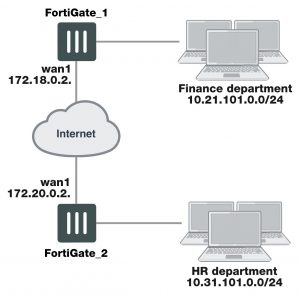
The Phase 1 configuration mainly defines the ends of the IPsec tunnel. The remote end is the remote gateway with which the FortiGate unit exchanges IPsec packets. The local end is the FortiGate interface that sends and receives IPsec packets.

The remote gateway can be:

  • A static IP address
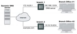
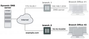
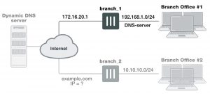
  • A domain name with a dynamic IP address
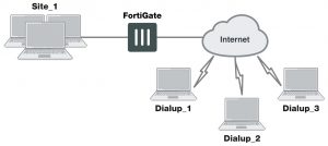
  • A dialup client

A statically addressed remote gateway is the simplest to configure. You specify the IP address. Unless restricted in the security policy, either the remote peer or a peer on the network behind the FortiGate unit can bring up the tunnel.

If the remote peer has a domain name and subscribes to a dynamic DNS service, you need to specify only the domain name. The FortiGate unit performs a DNS query to determine the appropriate IP address. Unless restricted in the security policy, either the remote peer or a peer on the network behind the FortiGate unit can bring up the tunnel.

If the remote peer is a dialup client, only the dialup client can bring up the tunnel. The IP address of the client is not known until it connects to the FortiGate unit. This configuration is a typical way to provide a VPN for client PCs running VPN client software such as the FortiClient Endpoint Security application.

The local end of the VPN tunnel, the Local Interface, is the FortiGate interface that sends and receives the IPsec packets. This is usually the public interface of the FortiGate unit that is connected to the Internet (typically the WAN1 port). Packets from this interface pass to the private network through a security policy.

By default, the local VPN gateway is the IP address of the selected Local Interface. If you are configuring an interface mode VPN, you can optionally use a secondary IP address of the Local Interface as the local gateway.


Choosing Main mode or Aggressive mode

The FortiGate unit and the remote peer or dialup client exchange Phase 1 parameters in either Main mode or Aggressive mode. This choice does not apply if you use IKE version 2, which is available only for route-based configurations.

  • In Main mode, the Phase 1 parameters are exchanged in multiple rounds with encrypted authentication information
  • In Aggressive mode, the Phase 1 parameters are exchanged in a single message with unencrypted authentication information.

Although Main mode is more secure, you must select Aggressive mode if there is more than one dialup Phase 1 configuration for the interface IP address, and the remote VPN peer or client is authenticated using an identifier local ID. Aggressive mode might not be as secure as Main mode, but the advantage to Aggressive mode is that it is faster than Main mode (since fewer packets are exchanged). Aggressive mode is typically used for remote access VPNs. But you would also use aggressive mode if one or both peers have dynamic external IP addresses. Descriptions of the peer options in this guide indicate whether Main or Aggressive mode is required.


Choosing the IKE version

If you create a route-based VPN, you have the option of selecting IKE version 2. Otherwise, IKE version 1 is used. IKEv2, defined in RFC 4306, simplifies the negotiation process that creates the security association (SA).

If you select IKEv2:

  • There is no choice in Phase 1 of Aggressive or Main mode.
  • FortiOS does not support Peer Options or Local ID.
  • Extended Authentication (XAUTH) is not available.
  • You can select only one Diffie-Hellman Group.
  • You can utilize EAP and MOBIKE.


IKEv2 cookie notification for IKE_SA_INIT

IKEv2 offers an optional exchange within IKE_SA_INIT (the initial exchange between peers when establishing a secure tunnel) as a reuslt of an inherent vulnerability in IPsec implementations, as described in RFC 5996.

Two expected attacks against IKE are state and CPU exhaustion, where the target is flooded with session initiation requests from forged IP addresses. These attacks can be made less effective if a responder uses minimal CPU and commits no state to an SA until it knows the initiator can receive packets at the address from which it claims to be sending them.

If the IKE_SA_INIT response includes the cookie notification, the initiator MUST then retry the IKE_SA_INIT request, and include the cookie notification containing the received data as the first payload, and all other payloads unchanged.

Upon detecting that the number of half-open IKEv2 SAs is above the threshold value, the VPN dialup server requires all future SA_INIT requests to include a valid cookie notification payload that the server sends back, in order to preserve CPU and memory resources.

For most devices, the threshold value is set to 500, half of the maximum 1,000 connections. This feature is enabled by default in FortiOS 5.4.

IKEv2 Quick Crash Detection

There is support for IKEv2 Quick Crash Detection as described in RFC 6290.

RFC 6290 describes a method in which an IKE peer can quickly detect that the gateway peer that it has and established an IKE session with has rebooted, crashed, or otherwise lost IKE state. When the gateway receives IKE messages or ESP packets with unknown IKE or IPsec SPIs, the IKEv2 protocol allows the gateway to send the peer an unprotected IKE message containing INVALID_IKE_SPI or INVALID_SPI notification payloads.

RFC 6290 introduces the concept of a QCD token, which is generated from the IKE SPIs and a private QCD secret, and exchanged between peers during the protected IKE AUTH exchange.


To add Quick Crash Detection – CLI Syntax

config system settings

set ike-quick-crash-detect [enable | disable]

end


Authenticating the FortiGate unit

The FortiGate unit can authenticate itself to remote peers or dialup clients using either a pre-shared key or an RSA Signature (certificate).


Authenticating the FortiGate unit with digital certificates

To authenticate the FortiGate unit using digital certificates, you must have the required certificates installed on the remote peer and on the FortiGate unit. The signed server certificate on one peer is validated by the presence of the root certificate installed on the other peer. If you use certificates to authenticate the FortiGate unit, you can also require the remote peers or dialup clients to authenticate using certificates.

For more information about obtaining and installing certificates, see the FortiOS User Authentication guide.


To authenticate the FortiGate unit using digital certificates

1. Go to VPN > IPsec Tunnels and create the new custom tunnel or edit an existing tunnel.

2. Edit the Phase 1 Proposal (if it is not available, you may need to click the Convert to Custom Tunnel button):

Name                                           Enter a name that reflects the origination of the remote connection. For interface mode, the name can be up to 15 characters long.

Remote Gateway                       Select the nature of the remote connection.

Each option changes the available fields you must configure. For more information, see Authenticating the FortiGate unit on page 1627.

Local Interface                          Select the interface that is the local end of the IPsec tunnel. For more information, see Authenticating the FortiGate unit on page 1627. The local interface is typically the WAN1 port.

Mode                                           Select a mode. It is easier to use Aggressive mode.

In Main mode, parameters are exchanged in multiple encrypted rounds. In Aggressive mode, parameters are exchanged in a single unencrypted message.

Aggressive mode must be used when the remote VPN peer or client has a dynamic IP address, or the remote VPN peer or client will be authenticated using an identifier (local ID).

For more information, see Authenticating the FortiGate unit on page 1627.

Authentication Method            Select Signature.

Certificate Name                        Select the name of the server certificate that the FortiGate unit will use to authenticate itself to the remote peer or dialup client during Phase 1 nego- tiations.

You must obtain and load the required server certificate before this selec- tion. See the FortiOS User Authentication guide. If you have not loaded any certificates, use the certificate named Fortinet_Factory.

Peer Options                             Peer options define the authentication requirements for remote peers or dialup clients. They are not for your FortiGate unit itself.

See Authenticating the FortiGate unit on page 1627.

Advanced                                   You can use the default settings for most Phase 1 configurations. Changes are required only if your network requires them. These settings includes IKE version, DNS server, P1 proposal encryption and authentication set- tings, and XAuth settings. See Authenticating the FortiGate unit on page 1627.

3. If you are configuring authentication parameters for a dialup user group, optionally define extended authentication

(XAuth) parameters in the Advanced section. See Authenticating the FortiGate unit on page 1627.

4. Select OK.


Authenticating the FortiGate unit with a pre-shared key

The simplest way to authenticate a FortiGate unit to its remote peers or dialup clients is by means of a pre-shared key. This is less secure than using certificates, especially if it is used alone, without requiring peer IDs or extended authentication (XAuth). Also, you need to have a secure way to distribute the pre-shared key to the peers.

If you use pre-shared key authentication alone, all remote peers and dialup clients must be configured with the same pre-shared key. Optionally, you can configure remote peers and dialup clients with unique pre-shared keys. On the FortiGate unit, these are configured in user accounts, not in the phase_1 settings. For more information, see Authenticating the FortiGate unit on page 1627.

The pre-shared key must contain at least 6 printable characters and best practices dictate that it be known only to network administrators. For optimum protection against currently known attacks, the key must consist of a minimum of 16 randomly chosen alphanumeric characters.

If you authenticate the FortiGate unit using a pre-shared key, you can require remote peers or dialup clients to authenticate using peer IDs, but not client certificates.


To authenticate the FortiGate unit with a pre-shared key

1. Go to VPN > IPsec Tunnels and create the new custom tunnel or edit an existing tunnel.

2. Edit the Phase 1 Proposal (if it is not available, you may need to click the Convert to Custom Tunnel button):

Name                                           Enter a name that reflects the origination of the remote connection.

Remote Gateway                       Select the nature of the remote connection. For more information, see Authenticating the FortiGate unit on page 1627.

Local Interface                          Select the interface that is the local end of the IPsec tunnel. For more information, see Authenticating the FortiGate unit on page 1627. The local interface is typically the WAN1 port.

Mode                                           Select Main or Aggressive mode.

In Main mode, the Phase 1 parameters are exchanged in multiple rounds with encrypted authentication information.

In Aggressive mode, the Phase 1 parameters are exchanged in single message with authentication information that is not encrypted.

When the remote VPN peer or client has a dynamic IP address, or the remote VPN peer or client will be authenticated using an identifier (local ID), you must select Aggressive mode if there is more than one dialup Phase 1 configuration for the interface IP address.

For more information, see Authenticating the FortiGate unit on page 1627.


Authentication Method            Select Preshared Key.

Preshared Key                          Enter the preshared key that the FortiGate unit will use to authenticate itself to the remote peer or dialup client during Phase 1 negotiations. You must define the same value at the remote peer or client. The key must con- tain at least 6 printable characters and best practices dictate that it only be known by network administrators. For optimum protection against currently known attacks, the key must consist of a minimum of 16 randomly chosen alphanumeric characters.

Peer options                              Peer options define the authentication requirements for remote peers or dialup clients, not for the FortiGate unit itself. You can require the use of peer IDs, but not client certificates. For more information, see Authentic- ating the FortiGate unit on page 1627.

Advanced                                   You can retain the default settings unless changes are needed to meet your specific requirements. See Authenticating the FortiGate unit on page 1627.

3. If you are configuring authentication parameters for a dialup user group, optionally define extended authentication

(XAuth) parameters. See Authenticating the FortiGate unit on page 1627.

4. Select OK.


Authenticating remote peers and clients

Certificates or pre-shared keys restrict who can access the VPN tunnel, but they do not identify or authenticate the remote peers or dialup clients. You have the following options for authentication:


Methods of authenticating remote VPN peers

Certificates or Pre-shared key        Local ID  User account pre- shared keys

Reference

Certificates                                                                                                       See Enabling VPN access for specific certificate holders on page 1630.

Either                                                        X                                                  See Enabling VPN access by peer identifier on page 1632.

Preshared key                                                                       X                     See Enabling VPN access with user accounts and pre-shared keys on page 1633.

Preshared key                                        X                          X

See Enabling VPN access with user accounts and pre-shared keys on page 1633.

Repeated Authentication in Internet Key Exchange (IKEv2) Protocol

This feature provides the option to control whether a device requires its peer to re-authenticate or whether re-key is sufficient. It does not influence the re-authentication or re-key behavior of the device itself, which is controlled by the peer (with the default being to re-key).

This solution is in response to RFC 4478. This solution is intended to limit the time that security associations (SAs) can be used by a third party who has gained control of the IPsec peer.


CLI Syntax:

config vpn ipsec phase1-interface edit p1

set reauth [enable | disable]

next end

disable: Disable IKE SA re-authentication.

enable: Enable IKE SA re-authentication.


Enabling VPN access for specific certificate holders

When a VPN peer or dialup client is configured to authenticate using digital certificates, it sends the Distinguished Name (DN) of its certificate to the FortiGate unit. This DN can be used to allow VPN access for the certificate holder. That is, a FortiGate unit can be configured to deny connections to all remote peers and dialup clients except the one having the specified DN.


Before you begin

The following procedures assume that you already have an existing Phase 1 configuration (see Authenticating remote peers and clients on page 1629). Follow the procedures below to add certificate-based authentication parameters to the existing configuration.

Before you begin, you must obtain the certificate DN of the remote peer or dialup client. If you are using the FortiClient application as a dialup client, refer to FortiClient online help for information about how to view the certificate DN. To view the certificate DN of a FortiGate unit, see To view server certificate information and obtain the local DN on page 1631.

Use the config user peer CLI command to load the DN value into the FortiGate configuration. For example, if a remote VPN peer uses server certificates issued by your own organization, you would enter information similar to the following:

config user peer edit DN_FG1000

set cn 192.168.2.160 set cn-type ipv4

end

The value that you specify to identify the entry (for example, DN_FG1000) is displayed in the Accept this peer certificate only list in the IPsec Phase 1 configuration when you return to the web-based manager.

If the remote VPN peer has a CA-issued certificate to support a higher level of credibility, you would enter information similar to the following in the CLI:

config user peer edit CA_FG1000

set ca CA_Cert_1

set subject FG1000_at_site1

end


The value that you specify to identify the entry (for example, CA_FG1000) is displayed in the Accept this peer certificate only list in the IPsec Phase 1 configuration when you return to the web-based manager. For more information about these CLI commands, see the “user” chapter of the FortiGate CLI Reference.

A group of certificate holders can be created based on existing user accounts for dialup clients. To create the user accounts for dialup clients, see the “User” chapter of the FortiGate Administration Guide. To create the certificate group afterward, use the config user peergrp CLI command. See the “user” chapter of the FortiGate CLI Reference.


To view server certificate information and obtain the local DN

1. Go to System > Certificates.

2. Note the CN value in the Subject field (for example, CN = 16.10.125, CN = info@fortinet.com, or CN = www.example.com).


To view CA root certificate information and obtain the CA certificate name

1. Go to System > Certificates > CA Certificates.

2. Note the value in the Name column (for example, CA_Cert_1).


Configuring certificate authentication for a VPN

With peer certificates loaded, peer users and peer groups defined, you can configure your VPN to authenticate users by certificate.


To enable access for a specific certificate holder or a group of certificate holders

1. At the FortiGate VPN server, go to VPN > IPsec Tunnels and create the new custom tunnel or edit an existing tunnel.

2. Edit the Phase 1 Proposal (if it is not available, you may need to click the Convert to Custom Tunnel button).

3. From the Authentication Method list, select RSA Signature.

4. From the Certificate Name list, select the name of the server certificate that the FortiGate unit will use to authenticate itself to the remote peer or dialup client

5. Under Peer Options, select one of these options:

  • To accept a specific certificate holder, select Accept this peer certificate only and select the name of the certificate that belongs to the remote peer or dialup client. The certificate DN must be added to the FortiGate configuration through CLI commands before it can be selected here. See Before you begin on page 1630.
  • To accept dialup clients who are members of a certificate group, select Accept this peer certificate group only and select the name of the group. The group must be added to the FortiGate configuration through CLI commands before it can be selected here. See Before you begin on page 1630.

6. If you want the FortiGate VPN server to supply the DN of a local server certificate for authentication purposes, select Advanced and then from the Local ID list, select the DN of the certificate that the FortiGate VPN server is to use.

7. Select OK.


Enabling VPN access by peer identifier

Whether you use certificates or pre-shared keys to authenticate the FortiGate unit, you can require that remote peers or clients have a particular peer ID. This adds another piece of information that is required to gain access to the VPN. More than one FortiGate/FortiClient dialup client may connect through the same VPN tunnel when the dialup clients share a preshared key and assume the same identifier.

A peer ID, also called local ID, can be up to 63 characters long containing standard regular expression characters. Local ID is set in phase1 Aggressive Mode configuration.

You cannot require a peer ID for a remote peer or client that uses a pre-shared key and has a static IP address.

To authenticate remote peers or dialup clients using one peer ID

1. At the FortiGate VPN server, go to VPN > IPsec Tunnels and create the new custom tunnel or edit an existing tunnel.

2. Edit the Phase 1 Proposal (if it is not available, you may need to click the Convert to Custom Tunnel button).

3. Select Aggressive mode in any of the following cases:

  • The FortiGate VPN server authenticates a FortiGate dialup client that uses a dedicated tunnel
  • A FortiGate unit has a dynamic IP address and subscribes to a dynamic DNS service
  • FortiGate/FortiClient dialup clients sharing the same preshared key and local ID connect through the same VPN tunnel

4. For the Peer Options, select This peer ID and type the identifier into the corresponding field.

5. Select OK.

To assign an identifier (local ID) to a FortiGate unit

Use this procedure to assign a peer ID to a FortiGate unit that acts as a remote peer or dialup client.

1. Go to VPN > IPsec Tunnels and create the new custom tunnel or edit an existing tunnel.

2. Edit the Phase 1 Proposal (if it is not available, you may need to click the Convert to Custom Tunnel button).

3. Select Advanced.

4. In the Local ID field, type the identifier that the FortiGate unit will use to identify itself.

5. Set Mode to Aggressive if any of the following conditions apply:

  • The FortiGate unit is a dialup client that will use a unique ID to connect to a FortiGate dialup server through a dedicated tunnel.
  • The FortiGate unit has a dynamic IP address, subscribes to a dynamic DNS service, and will use a unique ID to connect to the remote VPN peer through a dedicated tunnel.
  • The FortiGate unit is a dialup client that shares the specified ID with multiple dialup clients to connect to a FortiGate dialup server through the same tunnel.

6. Select OK.


To configure the FortiClient application

Follow this procedure to add a peer ID to an existing FortiClient configuration:

1. Start the FortiClient application.

2. Go to VPN > Connections, select the existing configuration.

3. Select Advanced > Edit > Advanced.

4. Under Policy, select Config.

5. In the Local ID field, type the identifier that will be shared by all dialup clients. This value must match the This peer ID value that you specified previously in the Phase 1 gateway configuration on the FortiGate unit.

6. Select OK to close all dialog boxes.

7. Configure all dialup clients the same way using the same preshared key and local ID.


Enabling VPN access with user accounts and pre-shared keys

You can permit access only to remote peers or dialup clients that have pre-shared keys and/or peer IDs configured in user accounts on the FortiGate unit.

If you want two VPN peers (or a FortiGate unit and a dialup client) to accept reciprocal connections based on peer IDs, you must enable the exchange of their identifiers when you define the Phase 1 parameters.

The following procedures assume that you already have an existing Phase 1 configuration (see Authenticating remote peers and clients on page 1629). Follow the procedures below to add ID checking to the existing configuration.

Before you begin, you must obtain the identifier (local ID) of the remote peer or dialup client. If you are using the FortiClient Endpoint Security application as a dialup client, refer to the Authenticating FortiClient Dialup Clients Technical Note to view or assign an identifier. To assign an identifier to a FortiGate dialup client or a FortiGate unit that has a dynamic IP address and subscribes to a dynamic DNS service, see To assign an identifier (local ID) to a FortiGate unit on page 1632.

If required, a dialup user group can be created from existing user accounts for dialup clients. To create the user accounts and user groups, see the User Authentication handbook chapter.

The following procedure supports FortiGate/FortiClient dialup clients that use unique preshared keys and/or peer IDs. The client must have an account on the FortiGate unit and be a member of the dialup user group.

The dialup user group must be added to the FortiGate configuration before it can be selected. For more information, see the User Authentication handbook chapter.

The FortiGate dialup server compares the local ID that you specify at each dialup client to the FortiGate user- account user name. The dialup-client preshared key is compared to a FortiGate user-account password.


To authenticate dialup clients using unique preshared keys and/or peer IDs

1. At the FortiGate VPN server, go to VPN > IPsec Tunnels and create the new custom tunnel or edit an existing tunnel.

2. Edit the Phase 1 Proposal (if it is not available, you may need to click the Convert to Custom Tunnel button).

3. If the clients have unique peer IDs, set Mode to Aggressive.

4. Clear the Preshared Key field.

The user account password will be used as the preshared key.

5. Select Peer ID from dialup group and then select the group name from the list of user groups.

6. Select OK.

Follow this procedure to add a unique pre-shared key and unique peer ID to an existing FortiClient configuration.


To configure FortiClient – pre-shared key and peer ID

1. Start the FortiClient Endpoint Security application.

2. Go to VPN > Connections, select the existing configuration.

3. Select Advanced > Edit.

4. In the Preshared Key field, type the FortiGate password that belongs to the dialup client (for example, 1234546).

The user account password will be used as the preshared key.

5. Select Advanced.

6. Under Policy, select Config.

7. In the Local ID field, type the FortiGate user name that you assigned previously to the dialup client (for example, FortiClient).

8. Select OK to close all dialog boxes.

Configure all FortiClient dialup clients this way using unique preshared keys and local IDs. Follow this procedure to add a unique pre-shared key to an existing FortiClient configuration.


To configure FortiClient – preshared key only

1. Start the FortiClient Endpoint Security application.

2. Go to VPN > Connections, select the existing configuration

3. Select Advanced > Edit.

4. In the Preshared Key field, type the user name, followed by a “+” sign, followed by the password that you specified previously in the user account settings on the FortiGate unit (for example, FC2+1FG6LK)

5. Select OK to close all dialog boxes.

Configure all the FortiClient dialup clients this way using their unique peer ID and pre-shared key values.


Defining IKE negotiation parameters

In Phase 1, the two peers exchange keys to establish a secure communication channel between them. As part of the Phase 1 process, the two peers authenticate each other and negotiate a way to encrypt further communications for the duration of the session. For more information see Defining IKE negotiation parameters on page 1635. The Phase 1 Proposal parameters select the encryption and authentication algorithms that are used to generate keys for protecting negotiations.


The IKE negotiation parameters determine:

  • Which encryption algorithms may be applied for converting messages into a form that only the intended recipient can read
  • Which authentication hash may be used for creating a keyed hash from a preshared or private key
  • Which Diffie-Hellman group (DH Group) will be used to generate a secret session key

Phase 1 negotiations (in main mode or aggressive mode) begin as soon as a remote VPN peer or client attempts to establish a connection with the FortiGate unit. Initially, the remote peer or dialup client sends the FortiGate unit a list of potential cryptographic parameters along with a session ID. The FortiGate unit compares those parameters to its own list of advanced Phase 1 parameters and responds with its choice of matching parameters to use for authenticating and encrypting packets. The two peers handle the exchange of encryption keys between them, and authenticate the exchange through a preshared key or a digital signature.


Generating keys to authenticate an exchange

The FortiGate unit supports the generation of secret session keys automatically using a Diffie-Hellman algorithm. These algorithms are defined in RFC 2409. The Keylife setting in the Phase 1 Proposal area determines the amount of time before the Phase 1 key expires. Phase 1 negotiations are re-keyed automatically when there is an active security association. See Dead peer detection on page 1638.

You can enable or disable automatic re-keying between IKE peers through the phase1-rekey attribute of the config system global CLI command. For more information, see the “System” chapter of the FortiGate CLI Reference.

When in FIPS-CC mode, the FortiGate unit requires DH key exchange to use values at least 3072 bits long. However most browsers need the key size set to 1024. You can set the minimum size of the DH keys in the CLI.

config system global set dh-params 3072

end

When you use a preshared key (shared secret) to set up two-party authentication, the remote VPN peer or client and the FortiGate unit must both be configured with the same preshared key. Each party uses a session key derived from the Diffie-Hellman exchange to create an authentication key, which is used to sign a known combination of inputs using an authentication algorithm (such as HMAC-MD5, HMAC-SHA-1, or HMAC-SHA-256). Hash-based Message Authentication Code (HMAC) is a method for calculating an authentication code using a hash function plus a secret key, and is defined in RFC 2104. Each party signs a different combination of inputs and the other party verifies that the same result can be computed.

For information regarding NP accelerated offloading of IPsec VPN authentication algorithms, please refer to the Hardware Acceleration handbook chapter.

When you use preshared keys to authenticate VPN peers or clients, you must distribute matching information to all VPN peers and/or clients whenever the preshared key changes.

As an alternative, the remote peer or dialup client and FortiGate unit can exchange digital signatures to validate each other’s identity with respect to their public keys. In this case, the required digital certificates must be installed on the remote peer and on the FortiGate unit. By exchanging certificate DNs, the signed server certificate on one peer is validated by the presence of the root certificate installed on the other peer.

The following procedure assumes that you already have a Phase 1 definition that describes how remote VPN peers and clients will be authenticated when they attempt to connect to a local FortiGate unit. For information about the Local ID and XAuth options, see Defining IKE negotiation parameters on page 1635 and Defining IKE negotiation parameters on page 1635. Follow this procedure to add IKE negotiation parameters to the existing definition.


Defining IKE negotiation parameters

1. Go to VPN > IPsec Tunnels and create the new custom tunnel or edit an existing tunnel.

2. Edit the Phase 1 Proposal (if it is not available, you may need to click the Convert to Custom Tunnel button).

3. Select Phase 1 Proposal and include the appropriate entries as follows:

Phase 1 Proposal                      Select the encryption and authentication algorithms that will be used to generate keys for protecting negotiations.

Add or delete encryption and authentication algorithms as required. Select a minimum of one and a maximum of three combinations. The remote peer must be configured to use at least one of the proposals that you define.

It is invalid to set both Encryption and Authentication to null.

Encryption                                 Select a symmetric-key algorithms:

NULL — Do not use an encryption algorithm.

DES — Digital Encryption Standard, a 64-bit block algorithm that uses a

56-bit key.

3DES — Triple-DES; plain text is encrypted three times by three keys.

AES128 — A 128-bit block algorithm that uses a 128-bit key. AES192 — A 128-bit block algorithm that uses a 192-bit key. AES256 — A 128-bit block algorithm that uses a 256-bit key.

Authentication                           You can select either of the following message digests to check the authen- ticity of messages during an encrypted session:

NULL — Do not use a message digest.

MD5 — Message Digest 5.

SHA1 — Secure Hash Algorithm 1 – a 160-bit message digest.

To specify one combination only, set the Encryption and Authentication options of the second combination to NULL. To specify a third com- bination, use the Add button beside the fields for the second combination.

For information regarding NP accelerated offloading of IPsec VPN authen- tication algorithms, please refer to the Hardware Acceleration handbook chapter.

DiffieHellman Group                Select one or more Diffie-Hellman groups from DH groups 1, 2, 5, and 14 through 21. When using aggressive mode, DH groups cannot be nego- tiated. By default, DH group 14 is selected, to provide sufficient protection for stronger cipher suites that include AES and SHA2. If you select multiple DH groups, the order they appear in the configuration is the order in which they are negotiates.

If both VPN peers (or a VPN server and its client) have static IP addresses and use aggressive mode, select a single DH group. The setting on the FortiGate unit must be identical to the setting on the remote peer or dialup client.

When the remote VPN peer or client has a dynamic IP address and uses aggressive mode, select up to three DH groups on the FortiGate unit and one DH group on the remote peer or dialup client. The setting on the remote peer or dialup client must be identical to one of the selections on the FortiGate unit.

If the VPN peer or client employs main mode, you can select multiple DH groups. At least one of the settings on the remote peer or dialup client must be identical to the selections on the FortiGate unit.

Keylife                                        Type the amount of time (in seconds) that will be allowed to pass before the IKE encryption key expires. When the key expires, a new key is gen- erated without interrupting service. The keylife can be from 120 to 172800 seconds.

Nat-traversal                              Enable this option if a NAT device exists between the local FortiGate unit and the VPN peer or client. The local FortiGate unit and the VPN peer or cli- ent must have the same NAT traversal setting (both selected or both cleared). When in doubt, enable NAT-traversal. See NAT traversal on page 1638.

Keepalive Frequency               If you enabled NAT traversal, enter a keepalive frequency setting. The value represents an interval from 0 to 900 seconds where the connection will be maintained with no activity. For additional security this value must be as low as possible. See NAT keepalive frequency on page 1638.

Dead Peer Detection                 Enable this option to reestablish VPN tunnels on idle connections and clean up dead IKE peers if required. This feature minimizes the traffic required to check if a VPN peer is available or unavailable (dead). See Dead peer detection on page 1638.


NAT traversal

Network Address Translation (NAT) is a way to convert private IP addresses to publicly routable Internet addresses and vise versa. When an IP packet passes through a NAT device, the source or destination address in the IP header is modified. FortiGate units support NAT version 1 (encapsulate on port 500 with non-IKE marker), version 3 (encapsulate on port 4500 with non-ESP marker), and compatible versions.

NAT cannot be performed on IPsec packets in ESP tunnel mode because the packets do not contain a port number. As a result, the packets cannot be demultiplexed. To work around this, the FortiGate unit provides a way to protect IPsec packet headers from NAT modifications. When the Nat-traversal option is enabled, outbound encrypted packets are wrapped inside a UDP IP header that contains a port number. This extra encapsulation allows NAT devices to change the port number without modifying the IPsec packet directly.

To provide the extra layer of encapsulation on IPsec packets, the Nat-traversal option must be enabled whenever a NAT device exists between two FortiGate VPN peers or a FortiGate unit and a dialup client such as FortiClient. On the receiving end, the FortiGate unit or FortiClient removes the extra layer of encapsulation before decrypting the packet.

Additionally, you can force IPsec to use NAT traversal. If NAT is set to Forced, the FortiGate will use a port value of zero when constructing the NAT discovery hash for the peer. This causes the peer to think it is behind a NAT device, and it will use UDP encapsulation for IPsec, even if no NAT is present. This approach maintains interoperability with any IPsec implementation that supports the NAT-T RFC.


NAT keepalive frequency

When a NAT device performs network address translation on a flow of packets, the NAT device determines how long the new address will remain valid if the flow of traffic stops (for example, the connected VPN peer may be idle). The device may reclaim and reuse a NAT address when a connection remains idle for too long.

To work around this, when you enable NAT traversal specify how often the FortiGate unit sends periodic keepalive packets through the NAT device in order to ensure that the NAT address mapping does not change during the lifetime of a session. To be effective, the keepalive interval must be smaller than the session lifetime value used by the NAT device.

The keepalive packet is a 138-byte ISAKMP exchange.


Dead peer detection

Sometimes, due to routing issues or other difficulties, the communication link between a FortiGate unit and a VPN peer or client may go down. Packets could be lost if the connection is left to time out on its own. The FortiGate unit provides a mechanism called Dead Peer Detection, sometimes referred to as gateway detection or ping server, to prevent this situation and reestablish IKE negotiations automatically before a connection times out: the active Phase 1 security associations are caught and renegotiated (rekeyed) before the Phase 1 encryption key expires.

By default, Dead Peer Detection sends probe messages every five seconds by default (see dpd- retryinterval in the FortiGate CLI Reference). If you are experiencing high network traffic, you can experiment with increasing the ping interval. However longer intervals will require more traffic to detect dead peers which will result in more traffic.

In the web-based manager, the Dead Peer Detection option can be enabled when you define advanced Phase 1 options. The config vpn ipsec phase1 CLI command supports additional options for specifying a retry count and a retry interval.

For more information about these commands and the related config router gwdetect CLI command, see the FortiGate CLI Reference.

For example, enter the following CLI commands to configure dead peer detection on the existing IPsec Phase 1 configuration called test to use 15 second intervals and to wait for 3 missed attempts before declaring the peer dead and taking action.

config vpn ipsec phase1 edit test

set dpd [disable | on-idle | on-demand]

set dpd-retryinveral 15 set dpd-retrycount 3

next end


Using XAuth authentication

Extended authentication (XAuth) increases security by requiring the remote dialup client user to authenticate in a separate exchange at the end of Phase 1. XAuth draws on existing FortiGate user group definitions and uses established authentication mechanisms such as PAP, CHAP, RADIUS, and LDAP to authenticate dialup clients. You can configure a FortiGate unit to function either as an XAuth server or an XAuth client.If the server or client is attempting a connection using XAuth and the other end is not using XAuth, the failed connection attempts that are logged will not specify XAuth as the reason.

Using the FortiGate unit as an XAuth server

A FortiGate unit can act as an XAuth server for dialup clients. When the Phase 1 negotiation completes, the FortiGate unit challenges the user for a user name and password. It then forwards the user’s credentials to an external RADIUS or LDAP server for verification.

If the user records on the RADIUS server have suitably configured Framed-IP-Address fields, you can assign client virtual IP addresses by XAuth instead of from a DHCP address range. See FortiClient dialup-client configurations on page 1702.

The authentication protocol to use for XAuth depends on the capabilities of the authentication server and the XAuth client:

  • Select PAP Server whenever possible.
  • You must select PAP Server for all implementations of LDAP and some implementations of Microsoft RADIUS.
  • Select Auto Server when the authentication server supports CHAP Server but the XAuth client does not. The FortiGate unit will use PAP to communicate with the XAuth client and CHAP to communicate with the authentication server. You can also use Auto Server to allows multiple source interfaces to be defined in an IPsec/IKE policy

Before you begin, create user accounts and user groups to identify the dialup clients that need to access the network behind the FortiGate dialup server. If password protection will be provided through an external RADIUS or LDAP server, you must configure the FortiGate dialup server to forward authentication requests to the authentication server. For information about these topics, see the FortiGate User Authentication Guide.


To authenticate a dialup user group using XAuth settings

1. At the FortiGate dialup server, go to VPN > IPsec Tunnels and create the new custom tunnel or edit an existing tunnel.

2. Edit the Phase 1 Proposal (if it is not available, you may need to click the Convert to Custom Tunnel button).

3. Under XAuth, select the Server Type setting, which determines the type of encryption method to use between the XAuth client, the FortiGate unit and the authentication server. Select one of the following options:

  • PAP Server —Password Authentication Protocol.
  • CHAP Server — Challenge-Handshake Authentication Protocol.
  • Auto Server —Use PAP between the XAuth client and the FortiGate unit, and CHAP between the FortiGate unit and the authentication server. This option allows multiple source interfaces to be defined in an IPsec/IKE policy.

4. From the User Group list, select the user group that needs to access the private network behind the FortiGate unit. The group must be added to the FortiGate configuration before it can be selected here. For multiple source interfaces to be defined in the IPsec/IKE policy, select Inherit Groups from Policy.

5. Select OK.


Using the FortiGate unit as an XAuth client

If the FortiGate unit acts as a dialup client, the remote peer, acting as an XAuth server, might require a username and password. You can configure the FortiGate unit as an XAuth client, with its own username and password, which it provides when challenged.


To configure the FortiGate dialup client as an XAuth client

1. At the FortiGate dialup client, go to VPN > IPsec Tunnels and create the new custom tunnel or edit an existing tunnel.

2. Edit the Phase 1 Proposal (if it is not available, you may need to click the Convert to Custom Tunnel button).

3. Under XAuth, select Enable as Client.

4. In the Username field, type the FortiGate PAP, CHAP, RADIUS, or LDAP user name that the FortiGate XAuth server will compare to its records when the FortiGate XAuth client attempts to connect.

5. In the Password field, type the password to associate with the user name.

6. Select OK.


Dynamic IPsec route control

You can add a route to a peer destination selector by using the add-route option, which is available for all dynamic IPsec Phases 1 and 2, for both policy-based and route-based IPsec VPNs. This option was previously only available when mode-cfg was enabled in Phase 1.

The add-route option adds a route to the FortiGate unit’s routing information base when the dynamic tunnel is negotiated. You can use the distance and priority options to set the distance and priority of this route. If this results in a route with the lowest distance, it is added to the FortiGate unit’s forwarding information base.

You can also enable add-route in any policy-based or route-based Phase 2 configuration that is associated with a dynamic (dialup) Phase 1. In Phase 2, add-route can be enabled, disabled, or set to use the same route as Phase 1.

The add-route feature is enabled by default and is configured in the CLI.


Syntax

Phase 1

config vpn ipsec edit <name>

set type dynamic

set add-route {enable | disable}

end end


Phase 2


config vpn ipsec {phase2 | phase2-interface}

edit <name>

set add-route {phase1 | enable | disable}

end end


Blocking IPsec SA Negotiation

For interface-based IPsec, IPsec SA negotiation blocking can only be removed if the peer offers a wildcard selector. If a wildcard selector is offered then the wildcard route will be added to the routing table with the distance/priority value configured in Phase 1 and, if that is the route with the lowest distance, it is installed into the forwarding information base.

In cases where this occurs, it is important to ensure that the distance value configured on Phase 1 is set appropriately.


Having trouble configuring your Fortinet hardware or have some questions you need answered? Check Out The Fortinet Guru Youtube Channel! Want someone else to deal with it for you? Get some consulting from Fortinet GURU!

IPsec Monitor

IPsec Monitor

You can use the IPsec Monitor to view activity on IPsec VPN tunnels and start or stop those tunnels. The display provides a list of addresses, proxy IDs, and timeout information for all active tunnels, including tunnel mode and route-based (interface mode) tunnels.

To view the IPsec monitor, go to Monitor > IPsec Monitor.

For dialup VPNs, the list provides status information about the VPN tunnels established by dialup clients, and their IP addresses.

For static IP or dynamic DNS VPNs, the list provides status and IP addressing information about VPN tunnels, active or not, to remote peers that have static IP addresses or domain names. You can also start and stop individual tunnels from the list.


Having trouble configuring your Fortinet hardware or have some questions you need answered? Check Out The Fortinet Guru Youtube Channel! Want someone else to deal with it for you? Get some consulting from Fortinet GURU!

Concentrator

Concentrator

In a hub-and-spoke configuration, policy-based VPN connections to a number of remote peers radiate from a single, central FortiGate unit. Site-to-site connections between the remote peers do not exist; however, you can establish VPN tunnels between any two of the remote peers through the FortiGate unit’s “hub”.

In a hub-and-spoke network, all VPN tunnels terminate at the hub. The peers that connect to the hub are known as “spokes”. The hub functions as a concentrator on the network, managing all VPN connections between the spokes. VPN traffic passes from one tunnel to the other through the hub.

You define a concentrator to include spokes in the hub-and-spoke configuration. You create the concentrator in

VPN > IPsec Concentrator and select Create New. A concentrator configuration specifies which spokes to include in an IPsec hub-and-spoke configuration.

Concentrator Name                   Type a name for the concentrator.

Available Tunnels                     A list of defined IPsec VPN tunnels. Select a tunnel from the list and then select the right arrow.

Members                                    A list of tunnels that are members of the concentrator. To remove a tunnel from the concentrator, select the tunnel and select the left arrow.


Having trouble configuring your Fortinet hardware or have some questions you need answered? Check Out The Fortinet Guru Youtube Channel! Want someone else to deal with it for you? Get some consulting from Fortinet GURU!