Transparent mode VPNs
This section describes transparent VPN configurations, in which two FortiGate units create a VPN tunnel between two separate private networks transparently.
The following topics are included in this section:
- Configuration overview
- Configure the VPN peers
Configuration overview
In transparent mode, all interfaces of the FortiGate unit except the management interface (which by default is assigned IP address 10.10.10.1/255.255.255.0) are invisible at the network layer. Typically, when a FortiGate unit runs in transparent mode, different network segments are connected to the FortiGate interfaces. The figure below shows the management station on the same subnet. The management station can connect to the FortiGate unit directly through the web-based manager.
Management station on internal network
An edge router typically provides a public connection to the Internet and one interface of the FortiGate unit is connected to the router. If the FortiGate unit is managed from an external address (see the figure below), the router must translate (NAT) a routable address to direct management traffic to the FortiGate management interface.
Management station on external network
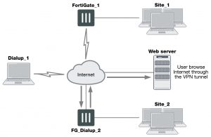
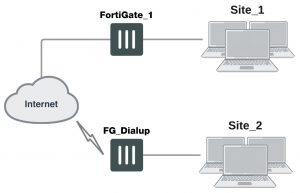
In a transparent VPN configuration, two FortiGate units create a VPN tunnel between two separate private networks transparently. All traffic between the two networks is encrypted and protected by FortiGate security policies.
Both FortiGate units may be running in transparent mode, or one could be running in transparent mode and the other running in NAT mode. If the remote peer is running in NAT mode, it must have a static public IP address.
VPNs between two FortiGate units running in transparent mode do not support inbound/outbound NAT (supported through CLI commands) within the tunnel. In addi- tion, a FortiGate unit running in transparent mode cannot be used in a hub-and-spoke configuration.
Encrypted packets from the remote VPN peer are addressed to the management interface of the local FortiGate unit. If the local FortiGate unit can reach the VPN peer locally, a static route to the VPN peer must be added to the routing table on the local FortiGate unit. If the VPN peer connects through the Internet, encrypted packets from the local FortiGate unit must be routed to the edge router instead. For information about how to add a static route to the FortiGate routing table, see the Advanced Routing Guide.
In the example configuration shown above, Network Address Translation (NAT) is enabled on the router. When an encrypted packet from the remote VPN peer arrives at the router through the Internet, the router performs inbound NAT and forwards the packet to the FortiGate unit. Refer to the software supplier’s documentation to configure the router.
If you want to configure a VPN between two FortiGate units running in transparent mode, each unit must have an independent connection to a router that acts as a gateway to the Internet, and both units must be on separate networks that have a different address space. When the two networks linked by the VPN tunnel have different address spaces (see the figure below), at least one router must separate the two FortiGate units, unless the packets can be redirected using ICMP (as shown in the following figure).
Link between two FortiGate units in transparent mode
In the figure below, interface C behind the router is the default gateway for both FortiGate units. Packets that cannot be delivered on Network_1 are routed to interface C by default. Similarly, packets that cannot be delivered on Network_2 are routed to interface C. In this case, the router must be configured to redirect packets destined for Network_1 to interface A and redirect packets destined for Network_2 to interface B.
ICMP redirecting packets to two FortiGate units in transparent mode
If there are additional routers behind the FortiGate unit (see the figure below) and the destination IP address of an inbound packet is on a network behind one of those routers, the FortiGate routing table must include routes to those networks. For example, in the following figure, the FortiGate unit must be configured with static routes to interfaces A and B in order to forward packets to Network_1 and Network_2 respectively.
Destinations on remote networks behind internal routers
Transparent VPN infrastructure requirements
- The local FortiGate unit must be operating in transparent mode.
- The management IP address of the local FortiGate unit specifies the local VPN gateway. The management IP address is considered a static IP address for the local VPN peer.
- If the local FortiGate unit is managed through the Internet, or if the VPN peer connects through the Internet, the edge router must be configured to perform inbound NAT and forward management traffic and/or encrypted packets to the FortiGate unit.
- If the remote peer is operating in NAT mode, it must have a static public IP address.
A FortiGate unit operating in transparent mode requires the following basic configuration to operate as a node on the IP network:
- The unit must have sufficient routing information to reach the management station.
- For any traffic to reach external destinations, a default static route to an edge router that forwards packets to the Internet must be present in the FortiGate routing table.
- When all of the destinations are located on the external network, the FortiGate unit may route packets using a single default static route. If the network topology is more complex, one or more static routes in addition to the default static route may be required in the FortiGate routing table.
Only policy-based VPN configurations are possible in transparent mode.
Before you begin
An IPsec VPN definition links a gateway with a tunnel and an IPsec policy. If your network topology includes more than one virtual domain, you must choose components that were created in the same virtual domain. Therefore, before you define a transparent VPN configuration, choose an appropriate virtual domain in which to create the required interfaces, security policies, and VPN components. For more information, see the Virtual Domains guide.
Configure the VPN peers
1. The local VPN peer need to operate in transparent mode.
To determine if your FortiGate unit is in transparent mode, go to the Dashboard > System Information widget. Select [change]. Select transparent for the Operation Mode. Two new fields will appear to enter the Management IP/Netmask, and the Default Gateway.
In transparent mode, the FortiGate unit is invisible to the network. All of its interfaces are on the same subnet and share the same IP address. You only have to configure a management IP address so that you can make configuration changes.
The remote VPN peer may operate in NAT mode or transparent mode.
2. At the local FortiGate unit, define the Phase 1 parameters needed to establish a secure connection with the remote peer. See Phase 1 parameters on page 1624. Select Advanced and enter these settings in particular:
Remote Gateway Select Static IP Address.
IP Address Type the IP address of the public interface to the remote peer. If the remote peer is a FortiGate unit running in transparent mode, type the IP address of the remote management interface.
Advanced Select Nat-traversal, and type a value into the Keepalive Frequency field. These settings protect the headers of encrypted packets from being altered by external NAT devices and ensure that NAT address mappings do not change while the VPN tunnel is open. For more information, see Phase 1 parameters on page 1624 and Phase 1 parameters on page 1624.
3. Define the Phase 2 parameters needed to create a VPN tunnel with the remote peer. See Phase 2 parameters on page 1642. Select the set of Phase 1 parameters that you defined for the remote peer. The name of the remote peer can be selected from the Static IP Address list.
4. Define the source and destination addresses of the IP packets that are to be transported through the VPN tunnel.
See Defining VPN security policies on page 1648. Enter these settings in particular:
- For the originating address (source address), enter the IP address and netmask of the private network behind the local peer network. for the management interface, for example, 10.10.10.0/24. This address needs to be a range to allow traffic from your network through the tunnel. Optionally select any for this address.
- For the remote address (destination address), enter the IP address and netmask of the private network behind the remote peer (for example, 192.168.10.0/24). If the remote peer is a FortiGate unit running in transparent mode, enter the IP address of the remote management interface instead.
5. Define an IPsec security policy to permit communications between the source and destination addresses. See
Defining VPN security policies on page 1648. Enter these settings in particular:
Incoming Interface Select the local interface to the internal (private) network.
Source Address Select the source address that you defined in Step 4.
Outgoing Interface Select the interface to the edge router. When you configure the IPsec secur- ity policy on a remote peer that operates in NAT mode, you select the pub- lic interface to the external (public) network instead.
Destination Address Select the destination address that you defined in Step 4.
VPN Tunnel Select Use Existing and select the name of the Phase 2 tunnel con- figuration that you created in Step 3 from the drop-down list.
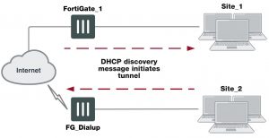
Select Allow traffic to be initiated from the remote site to enable traffic from the remote network to initiate the tunnel.
6. Place the policy in the policy list above any other policies having similar source and destination addresses.
7. Define another IPsec security policy to permit communications between the source and destination addresses in the opposite direction. This security policy and the previous one form a bi-directional policy pair. See Defining VPN security policies on page 1648. Enter these settings in particular:
Incoming Interface Select the interface to the edge router. When you configure the IPsec secur- ity policy on a remote peer that operates in NAT mode, you select the pub- lic interface to the external (public) network instead.
Source Address Select the destination address that you defined in Step 4..
Outgoing Interface Select the local interface to the internal (private) network.
Destination Address Select the source address that you defined in Step 4.
VPN Tunnel Select Use Existing and select the name of the Phase 2 tunnel con- figuration that you created in Step 3 from the drop-down list.
Select Allow traffic to be initiated from the remote site to enable traffic from the remote network to initiate the tunnel.
8. Repeat this procedure at the remote FortiGate unit to create bidirectional security policies. Use the local interface and address information local to the remote FortiGate unit.
For more information on transparent mode, see the System Administration Guide.