Category Archives: FortiOS

Redundant VPN configurations

Redundant VPN configurations

This section discusses the options for supporting redundant and partially redundant IPsec VPNs, using route- based approaches.

The following topics are included in this section: Configuration overview

General configuration steps

Configure the VPN peers – route-based VPN Redundant route-based VPN configuration example Partially-redundant route-based VPN example Creating a backup IPsec interface


Configuration overview

A FortiGate unit with two interfaces connected to the Internet can be configured to support redundant VPNs to the same remote peer. If the primary connection fails, the FortiGate unit can establish a VPN using the other connection.

Redundant tunnels do not support Tunnel Mode or manual keys. You must use Interface Mode.

A fully-redundant configuration requires redundant connections to the Internet on both peers. The figure below shows an example of this. This is useful to create a reliable connection between two FortiGate units with static IP addresses.

When only one peer has redundant connections, the configuration is partially-redundant. For an example of this, see Configuration overview on page 1734. This is useful to provide reliable service from a FortiGate unit with static IP addresses that accepts connections from dialup IPsec VPN clients.

In a fully-redundant VPN configuration with two interfaces on each peer, four distinct paths are possible for VPN traffic from end to end. Each interface on a peer can communicate with both interfaces on the other peer. This ensures that a VPN will be available as long as each peer has one working connection to the Internet.

You configure a VPN and an entry in the routing table for each of the four paths. All of these VPNs are ready to carry data. You set different routing distances for each route and only the shortest distance route is used. If this route fails, the route with the next shortest distance is used.

The redundant configurations described in this chapter use route-based VPNs, otherwise known as virtual IPsec interfaces. This means that the FortiGate unit must operate in NAT mode. You must use auto-keying. A VPN that is created using manual keys cannot be included in a redundant-tunnel configuration.

The configuration described here assumes that your redundant VPNs are essentially equal in cost and capability. When the original VPN returns to service, traffic continues to use the replacement VPN until the replacement VPN fails. If your redundant VPN uses more expensive facilities, you want to use it only as a backup while the main VPN is down. For information on how to do this, see Configuration overview on page 1734.


Example redundant-tunnel configuration

A VPN that is created using manual keys cannot be included in a redundant-tunnel configuration.


General configuration steps

A redundant configuration at each VPN peer includes:

  • One Phase 1 configuration (virtual IPsec interface) for each path between the two peers. In a fully-meshed redundant configuration, each network interface on one peer can communicate with each network interface on the remote peer. If both peers have two public interfaces, this means that each peer has four paths, for example.
  • One Phase 2 definition for each Phase 1 configuration.
  • One static route for each IPsec interface, with different distance values to prioritize the routes.
  • Two Accept security policies per IPsec interface, one for each direction of traffic.
  • Dead peer detection enabled in each Phase 1 definition.

The procedures in this section assume that two separate interfaces to the Internet are available on each VPN peer.


Having trouble configuring your Fortinet hardware or have some questions you need answered? Check Out The Fortinet Guru Youtube Channel! Want someone else to deal with it for you? Get some consulting from Fortinet GURU!

Secure VPN Internet-browsing configuration

Internet-browsing configuration

This section explains how to support secure web browsing performed by dialup VPN clients, and/or hosts behind a remote VPN peer. Remote users can access the private network behind the local FortiGate unit and browse the Internet securely. All traffic generated remotely is subject to the security policy that controls traffic on the private network behind the local FortiGate unit.

The following topics are included in this section:

  • Configuration overview
  • Creating an Internet browsing security policy
  • Routing all remote traffic through the VPN tunnel


Configuration overview

A VPN provides secure access to a private network behind the FortiGate unit. You can also enable VPN clients to access the Internet securely. The FortiGate unit inspects and processes all traffic between the VPN clients and hosts on the Internet according to the Internet browsing policy. This is accomplished even though the same FortiGate interface is used for both encrypted VPN client traffic and unencrypted Internet traffic.

In the figure below, FortiGate_1 enables secure Internet browsing for FortiClient Endpoint Security users such as Dialup_1 and users on the Site_2 network behind FortiGate_2, which could be a VPN peer or a dialup client.


Example Internet-browsing configuration

internet-browsing-configuration

You can adapt any of the following configurations to provide secure Internet browsing:

  • A gateway-to-gateway configuration (see Gateway-to-gateway configurations on page 1655)
  • A FortiClient dialup-client configuration (see FortiClient dialup-client configurations on page 1702)
  • A FortiGate dialup-client configuration (see FortiGate dialup-client configurations on page 1716)

The procedures in this section assume that one of these configurations is in place, and that it is operating properly.

To create an internet-browsing configuration based on an existing gateway-to-gateway configuration, you must edit the gateway-to-gateway configuration as follows:

  • On the FortiGate unit that will provide Internet access, create an Internet browsing security policy. See Configuration overview on page 1729, below.
  • Configure the remote peer or client to route all traffic through the VPN tunnel. You can do this on a FortiGate unit or on a FortiClient Endpoint Security application. See Configuration overview on page 1729.


Creating an Internet browsing security policy

On the FortiGate unit that acts as a VPN server and will provide secure access to the Internet, you must create an Internet browsing security policy. This policy differs depending on whether your gateway-to-gateway configuration is policy-based or route-based.


To create an Internet browsing policy – policy-based VPN

1. Go to Policy & Objects > IPv4 Policy and select Create New.

2. Enter the following information and then select OK:

Incoming Interface                   The interface to which the VPN tunnel is bound.

Source Address                        All

Outgoing Interface                   The interface to which the VPN tunnel is bound.

Destination Address                 The internal range of address of the remote spoke site.

VPN Tunnel                                Select Use Existing and select the tunnel that provides access to the private network behind the FortiGate unit.

Allow traffic to be initiated from the remote site Enable

Inbound NAT                             Enable

3. Enable inbound NAT in the CLI.

config firewall policy edit <policy_number>

set natinbound enable

end


To create an Internet browsing policy – route-based VPN

1. Go to Policy & Objects > IPv4 Policy and select Create New.

2. Leave the Policy Type as Firewall and leave the Policy Subtype as Address.

3. Enter the following information and then select OK:

Incoming Interface                   The IPsec VPN interface.

Source Address                        All

Outgoing Interface                   The interface that connects to the Internet. The virtual IPsec interface is configured on this physical interface.

Destination Address                 The internal range of address of the remote spoke site.

Action                                         ACCEPT

Enable NAT                                Enable

The VPN clients must be configured to route all Internet traffic through the VPN tunnel.


Routing all remote traffic through the VPN tunnel

To make use of the Internet browsing configuration on the VPN server, the VPN peer or client must route all traffic through the VPN tunnel. Usually, only the traffic destined for the private network behind the FortiGate VPN server is sent through the tunnel.

The remote end of the VPN can be a FortiGate unit that acts as a peer in a gateway-to-gateway configuration, or a FortiClient application that protects an individual client PC.

  • To configure a remote peer FortiGate unit for Internet browsing via VPN, see Configuring a FortiGate remote peer to support Internet browsing on page 1732.
  • To configure a FortiClient Endpoint Security application for Internet browsing via VPN, see Configuring a FortiClient application to support Internet browsing on page 1732.

These procedures assume that your VPN connection to the protected private network is working and that you have configured the FortiGate VPN server for Internet browsing as described in Routing all remote traffic through the VPN tunnel on page 1731.


Configuring a FortiGate remote peer to support Internet browsing

The configuration changes to send all traffic through the VPN differ for policy-based and route-based VPNs.


To route all traffic through a policy-based VPN

1. At the FortiGate dialup client, go to Policy & Objects > IPv4 Policy.

2. Select the IPsec security policy and then select Edit.

3. From the Destination Address list, select all.

4. Select OK.

Packets are routed through the VPN tunnel, not just those destined for the protected private network.


To route all traffic through a route-based VPN

1. At the FortiGate dialup client, go to Network > Static Routes.

2. Select the default route (destination IP 0.0.0.0) and then select Edit. If there is no default route, select Create

New. Enter the following information and select OK:

Destination IP/Mask                 0.0.0.0/0.0.0.0

Device                                         Select the IPsec virtual interface.

Distance                                     Leave at default.

All packets are routed through the VPN tunnel, not just packets destined for the protected private network.


Configuring a FortiClient application to support Internet browsing

By default, the FortiClient application configures the PC so that traffic destined for the remote protected network passes through the VPN tunnel but all other traffic is sent to the default gateway. You need to modify the FortiClient settings so that it configures the PC to route all outbound traffic through the VPN.


To route all traffic through VPN – FortiClient application

1. At the remote host, start FortiClient.

2. Go to VPN > Connections.

3. Select the definition that connects FortiClient to the FortiGate dialup server.

4. Select Advanced and then select Edit.

5. In the Edit Connection dialog box, select Advanced.

6. In the Remote Network group, select Add.

7. In the IP and Subnet Mask fields, type 0.0.0/0.0.0.0 and select OK.

The address is added to the Remote Network list. The first destination IP address in the list establishes a VPN tunnel. The second destination address (0.0.0.0/0.0.0.0 in this case) forces all other traffic through the VPN tunnel.

8. Select OK.


Having trouble configuring your Fortinet hardware or have some questions you need answered? Check Out The Fortinet Guru Youtube Channel! Want someone else to deal with it for you? Get some consulting from Fortinet GURU!

Supporting IKE Mode config clients

Supporting IKE Mode config clients

IKE Mode Config is an alternative to DHCP over IPsec. A FortiGate unit can be configured as either an IKE Mode Config server or client. This chapter contains the following sections:

  • Automatic configuration overview IKE Mode Config overview Configuring IKE Mode Config
  • Example FortiGate unit as IKE Mode Config server
  • Example FortiGate unit as IKE Mode Config client


Automatic configuration overview

VPN configuration for remote clients is simpler if it is automated. Several protocols support automatic configuration:

  • The Fortinet FortiClient Endpoint Security application can completely configure a VPN connection with a suitably configured FortiGate unit given only the FortiGate unit’s address. This protocol is exclusive to Fortinet. For more information, see FortiClient dialup-client configurations on page 1702.
  • DHCP over IPsec can assign an IP address, Domain, DNS and WINS addresses. The user must first configure
  • IPsec parameters such as gateway address, encryption and authentication algorithms.
  • IKE Mode Config can configure host IP address, Domain, DNS and WINS addresses. The user must first configure IPsec parameters such as gateway address, encryption and authentication algorithms. Several network equipment vendors support IKE Mode Config, which is described in the ISAKMP Configuration Method document draft-dukes- ike-mode-cfg-02.txt.

This chapter describes how to configure a FortiGate unit as either an IKE Mode Config server or client.


IKE Mode Config overview

Dialup VPN clients connect to a FortiGate unit that acts as a VPN server, providing the client the necessary configuration information to establish a VPN tunnel. The configuration information typically includes a virtual IP address, netmask, and DNS server address.

IKE Mode Config is available only for VPNs that are route-based, also known as interface-based. A FortiGate unit can function as either an IKE Configuration Method server or client. IKE Mode Config is configurable only in the CLI.


Configuring IKE Mode Config

IKE Mode Config is configured with the CLI command config vpn ipsec phase1-interface. The mode-cfg variable enables IKE Mode Config. The  type field determines whether you are creating an IKE Mode Config server or a client. Setting  type to  dynamic creates a server configuration, otherwise the configuration is a client.


Configuring an IKE Mode Config client

If the FortiGate unit will connect as a dialup client to a remote gateway that supports IKE Mode Config, the relevant vpn ipsec phase1-interface variables are as follows:

Variable                                    Description

ike-version 1          IKE v1 is the default for FortiGate IPsec VPNs.

IKE Mode Config is also compatible with IKE v2 (RFC 4306). Use syntax ike-version 2.

mode-cfg enable        Enable IKE Mode Config.

type {ddns | static}   If you set  type to  dynamic, an IKE Mode Config server is created.

assign-ip {enable | disable}

Enable to request an IP address from the server.

interface <interface_

name>

proposal <encryption_

combination>

This is a regular IPsec VPN field. Specify the physical, aggregate, or VLAN interface to which the IPsec tunnel will be bound.

This is a regular IPsec VPN field that determines the encryption and authen- tication settings that the client will accept. For more information, see Phase 1 parameters on page 1624.

mode-cfg-ip-version

{4|6}

Select if the Method client receives an IPv4 or IPv6 IP address. The default is  4. the  ip-version setting matches this variable’s value.

ip-version <4 | 6>     This is a regular IPsec VPN field. By default, IPsec VPNs use IPv4 address- ing. You can set  ip-version to  6 to create a VPN with IPv6 address- ing.

For a complete list of available variables, see the CLI Reference.


Configuring an IKE Mode Config server

If the FortiGate unit will accept connection requests from dialup clients that support IKE Mode Config, the following  vpn ipsec phase1-interface settings are required before any other configuration is attempted:


Variable                                    Description

ike-version 1          IKE v1 is the default for FortiGate IPsec VPNs.

IKE Mode Config is also compatible with IKE v2 (RFC 4306). Use syntax ike-version 2.

mode-cfg enable        Enable IKE Mode Config.

type dynamic           Any other setting creates an IKE Mode Config client.


Variable                                    Description

interface <interface_

name>

This is a regular IPsec VPN field. Specify the physical, aggregate, or VLAN

interface to which the IPsec tunnel will be bound.


proposal <encryption_

combination>

This is a regular IPsec VPN field that determines the encryption and authen- tication settings that the server will accept. For more information, see Phase 1 parameters on page 1624.

ip-version <4 | 6>     This is a regular IPsec VPN field. By default, IPsec VPNs use IPv4 address- ing. You can set  ip-version to  6 to create a VPN with IPv6 addressing.


For a complete list of available variables, see the CLI Reference. After you have enabled the basic configuration, you can configure:

  • IP address assignment for clients
  • DNS and WINS server assignment


IP address assignment

Usually you will want to assign IP addresses to clients. The simplest method is to assign addresses from a specific range, similar to a DHCP server.


If your clients are authenticated by a RADIUS server, you can obtain the user’s IP address assignment from the Framed-IP-Address attribute. The user must be authenticated using XAuth.

IKE Mode Config can also use a remote DHCP server to assign the client IP addresses. Up to eight addresses can be selected for either IPv4 or IPv6. After the DHCP proxy has been configured, the assign-ip-from command is used to assign IP addresses via DHCP.


To assign IP addresses from an address range – CLI

If your VPN uses IPv4 addresses,


config vpn ipsec phase1-interface edit vpn1

set mode-cfg-ipversion 4 set assign-ip enable

set assign-ip-type ip

set assign-ip-from range

set ipv4-start-ip <range_start>

set ipv4-end-ip <range_end>

set ipv4-netmask <netmask>

end


If your VPN uses IPv6 addresses,


config vpn ipsec phase1-interface edit vpn1

set mode-cfg-ipversion 6 set assign-ip enable

set assign-ip-type ip

set assign-ip-from range

set ipv6-start-ip <range_start>

set ipv6-end-ip <range_end>

end


To assign IP addresses from a RADIUS server – CLI

The users must be authenticated by a RADIUS server and assigned to the FortiGate user group <grpname>. Since the IP address will not be static, type is set to dynamic, and mode-cfg is enabled. This is IKE Configuration Method so that compatible clients can configure themselves with settings that the FortiGate unit provides.


config vpn ipsec phase1-interface edit vpn1

set type dynamic

set mode-cfg enable set assign-ip enable

set assign-ip-from usrgrp set xauthtype auto

set authusrgrp <grpname>

end


To assign IP address from DHCP – CLI

The DHCP proxy must first be enabled for IKE Mode Config to use DHCP to assign the VPN client IP address(es).


config system settings set dhcp-proxy enable

set dhcp-server-ip [ipv4 address]

set dhcp6-server-ip [ipv6-address]


(Up to 8 server addresses can be configured)


end


config vpn ipsec phase1-interface edit vpn1

set mode-cfg enable

set assign-ip-from dhcp next

end


Certificate groups

IKE certificate groups consisting of up to four RSA certificates can be used in IKE Phase 1. Since CA and local certificates are global, the IKE daemon loads them once for all VDOMs and indexes them into trees based on subject and public key hash (for CA certificates), or certificate name (for local certicates). Certifcates are linked together based on the issuer, and certificate chains are built by traversing these links. This reduces the need to keep multiple copies of certificates that could exist in multiple chains.


IKE certificate groups can be configured through the CLI.


Configuring the IKE local ID (CLI):


config vpn certificate local edit <name>

set ike-localid <string>

set ike-localid-type {asnldn | fqdn}

end


Example FortiGate unit as IKE Mode Config server

In this example, the FortiGate unit assigns IKE Mode Config clients addresses in the range of 10.11.101.160 through 10.11.101.180. DNS and WINS server addresses are also provided. The public interface of the FortiGate unit is Port 1.

When IKE Mode-Configuration is enabled, multiple server IPs can be defined in IPsec Phase 1.

The ipv4-split-include variable specifies a firewall address that represents the networks to which the clients will have access. This destination IP address information is sent to the clients.

Only the CLI fields required for IKE Mode Config are shown here. For detailed information about these variables, see the FortiGate CLI Reference.


config vpn ipsec phase1-interface edit “vpn-p1”

set type dynamic

set interface “wan1” set xauthtype auto set mode aggressive set mode-cfg enable

set proposal 3des-sha1 aes128-sha1 set dpd disable

set dhgrp 2

set xauthexpire on-rekey set authusrgrp “FG-Group1”

set ipv4-start-ip 10.10.10.10 set ipv4-end-ip 10.10.10.20 set ipv4-dns-server1 1.1.1.1 set ipv4-dns-server2 2.2.2.2 set ipv4-dns-server3 3.3.3.3 set ipv4-wins-server1 4.4.4.4 set ipv4-wins-server2 5.5.5.5 set domain “fgt1c-domain”

set banner “fgt111C-banner”

set backup-gateway “100.100.100.1” “host1.com” “host2” set ipv4-split-include OfficeLAN

end


Example FortiGate unit as IKE Mode Config client

In this example, the FortiGate unit connects to a VPN gateway with a static IP address that can be reached through Port 1. Only the port, gateway and proposal information needs to be configured. All other configuration information will come from the IKE Mode Config server.


config vpn ipsec phase1-interface edit vpn1

set ip-version 4 set type static

set remote-gw <gw_address>

set interface port 1

set proposal 3des-sha1 aes128-sha1 set mode-cfg enable

set mode-cfg-ipversion 4 set assign-ip enable

end


Having trouble configuring your Fortinet hardware or have some questions you need answered? Check Out The Fortinet Guru Youtube Channel! Want someone else to deal with it for you? Get some consulting from Fortinet GURU!

FortiGate dialup-client configurations

FortiGate dialup-client configurations

This section explains how to set up a FortiGate dialup-client IPsec VPN. In a FortiGate dialup-client configuration, a FortiGate unit with a static IP address acts as a dialup server and a FortiGate unit having a dynamic IP address initiates a VPN tunnel with the FortiGate dialup server.

  • The following topics are included in this section: Configuration overview
  • FortiGate dialup-client configuration steps
  • Configure the server to accept FortiGate dialup-client connections
  • Configure the FortiGate dialup client


Configuration overview

A dialup client can be a FortiGate unit. The FortiGate dialup client typically obtains a dynamic IP address from an ISP through the Dynamic Host Configuration Protocol (DHCP) or Point-to-Point Protocol over Ethernet (PPPoE) before initiating a connection to a FortiGate dialup server.


Example FortiGate dialup-client configuration

fortigate-dial-up-configuration

In a dialup-client configuration, the FortiGate dialup server does not rely on a Phase 1 remote gateway address to establish an IPsec VPN connection with dialup clients. As long as authentication is successful and the IPsec security policy associated with the tunnel permits access, the tunnel is established.

Several different ways to authenticate dialup clients and restrict access to private networks based on client credentials are available. To authenticate FortiGate dialup clients and help to distinguish them from FortiClient dialup clients when multiple clients will be connecting to the VPN through the same tunnel, best practices dictate that you assign a unique identifier (local ID or peer ID) to each FortiGate dialup client. For more information, see Phase 1 parameters on page 1624.

Whenever you add a unique identifier (local ID) to a FortiGate dialup client for iden- tification purposes, you must select Aggressive mode on the FortiGate dialup server and also specify the identifier as a peer ID on the FortiGate dialup server. For more information, see Phase 1 parameters on page 1624.

Users behind the FortiGate dialup server cannot initiate the tunnel because the FortiGate dialup client does not have a static IP address. After the tunnel is initiated by users behind the FortiGate dialup client, traffic from the private network behind the FortiGate dialup server can be sent to the private network behind the FortiGate dialup client.

Encrypted packets from the FortiGate dialup client are addressed to the public interface of the dialup server. Encrypted packets from the dialup server are addressed either to the public IP address of the FortiGate dialup client (if the dialup client connects to the Internet directly), or if the FortiGate dialup client is behind a NAT device, encrypted packets from the dialup server are addressed to the public IP address of the NAT device.

If a router with NAT capabilities is in front of the FortiGate dialup client, the router must be NAT-T compatible for encrypted traffic to pass through the NAT device. For more information, see Phase 1 parameters on page 1624.

When the FortiGate dialup server decrypts a packet from the FortiGate dialup client, the source address in the IP header may be one of the following values, depending on the configuration of the network at the far end of the tunnel:

  • If the FortiGate dialup client connects to the Internet directly, the source address will be the private IP address of a host or server on the network behind the FortiGate dialup client.
  • If the FortiGate dialup client is behind a NAT device, the source address will be the public IP address of the NAT device.

In some cases, computers on the private network behind the FortiGate dialup client may (by co-incidence) have IP addresses that are already used by computers on the network behind the FortiGate dialup server. In this type of situation (ambiguous routing), conflicts may occur in one or both of the FortiGate routing tables and traffic destined for the remote network through the tunnel may not be sent.

In many cases, computers on the private network behind the FortiGate dialup client will most likely obtain IP addresses from a local DHCP server behind the FortiGate dialup client. However, unless the local and remote networks use different private network address spaces, unintended ambiguous routing and IP-address overlap issues may arise.

To avoid these issues, you can configure FortiGate DHCP relay on the dialup client instead of using a DHCP server on the network behind the dialup client. The FortiGate dialup client can be configured to relay DHCP requests from the local private network to a DHCP server that resides on the network behind the FortiGate dialup server. You configure the FortiGate dialup client to pass traffic from the local private network to the remote network by enabling FortiGate DHCP relay on the FortiGate dialup client interface that is connected to the local private network.

Afterward, when a computer on the network behind the dialup client broadcasts a DHCP request, the dialup client relays the message through the tunnel to the remote DHCP server. The remote DHCP server responds with a private IP address for the computer. To avoid ambiguous routing and network overlap issues, the IP addresses assigned to computers behind the dialup client cannot match the network address space used by the private network behind the FortiGate dialup server.


Preventing network overlap in a FortiGate dialup-client configuration

preventing-network-overlap-in-a-fortigate-dialup-connection

When the DHCP server resides on the private network behind the FortiGate dialup server, the IP destination address specified in the IPsec security policy on the FortiGate dialup client must refer to that network.

You must add a static route to the DHCP server FortiGate unit if it is not directly con- nected to the private network behind the FortiGate dialup server; its IP address does not match the IP address of the private network. Also, the destination address in the IPsec security policy on the FortiGate dialup client must refer to the DHCP server address. The DHCP server must be configured to assign a range of IP addresses dif- ferent from the DHCP server’s local network, and also different from the private net- work addresses behind the FortiGate dialup server. See Dynamic DNS configuration on page 1688.


FortiGate dialup-client infrastructure requirements


The requirements are:

  • The FortiGate dialup server must have a static public IP address.
  • NAT mode is required if you want to create a route-based VPN.
  • The FortiGate dialup server may operate in either NAT mode or transparent mode to support a policy-based VPN.
  • Computers on the private network behind the FortiGate dialup client can obtain IP addresses either from a DHCP server behind the FortiGate dialup client, or a DHCP server behind the FortiGate dialup server.
  • If the DHCP server resides on the network behind the dialup client, the DHCP server must be configured to assign IP addresses that do not match the private network behind the FortiGate dialup server.
  • If the DHCP server resides on the network behind the FortiGate dialup server, the DHCP server must be configured to assign IP addresses that do not match the private network behind the FortiGate dialup client.


FortiGate dialup-client configuration steps

The procedures in this section assume that computers on the private network behind the FortiGate dialup client obtain IP addresses from a local DHCP server. The assigned IP addresses do not match the private network behind the FortiGate dialup server.

In situations where IP-address overlap between the local and remote private networks is likely to occur, FortiGate DHCP relay can be configured on the FortiGate dialup cli- ent to relay DHCP requests to a DHCP server behind the FortiGate dialup server. For more information, see FortiClient dialup-client configurations on page 1702.


Configuring dialup client capability for FortiGate dialup clients involves the following general configuration steps:

  • Determine which IP addresses to assign to the private network behind the FortiGate dialup client, and add the IP addresses to the DHCP server behind the FortiGate dialup client. Refer to the software supplier’s documentation to configure the DHCP server.
  • Configure the FortiGate dialup server. See FortiGate dialup-client configuration steps on page 1718.
  • Configure the FortiGate dialup client. See FortiGate dialup-client configuration steps on page 1718.


Configure the server to accept FortiGate dialup-client connections

Before you begin, optionally reserve a unique identifier (peer ID) for the FortiGate dialup client. The dialup client will supply this value to the FortiGate dialup server for authentication purposes during the IPsec Phase 1 exchange. In addition, the value will enable you to distinguish FortiGate dialup-client connections from FortiClient dialup-client connections. The same value must be specified on the dialup server and on the dialup client.

1. At the FortiGate dialup server, define the Phase 1 parameters needed to authenticate the FortiGate dialup client and establish a secure connection. See Phase 1 parameters on page 1624. Enter these settings in particular:

Name                                           Enter a name to identify the VPN tunnel. This name appears in Phase 2 configurations, security policies and the VPN monitor.

Remote Gateway                       Select Dialup User.

Local Interface                          Select the interface through which clients connect to the FortiGate unit.

Mode                                           If you will be assigning an ID to the FortiGate dialup client, select Aggress– ive.

Peer Options                             If you will be assigning an ID to the FortiGate dialup client, select This

peer ID and type the identifier that you reserved for the FortiGate dialup cli- ent into the adjacent field.

2. Define the Phase 2 parameters needed to create a VPN tunnel with the FortiGate dialup client. See Phase 2 parameters on page 1642. Enter these settings in particular:

Name                                           Enter a name to identify this Phase 2 configuration.

Phase 1                                       Select the name of the Phase 1 configuration that you defined.

3. Define names for the addresses or address ranges of the private networks that the VPN links. See Defining VPN

security policies on page 1648. Enter these settings in particular:

  • Define an address name for the server, host, or network behind the FortiGate dialup server.
  • Define an address name for the private network behind the FortiGate dialup client.

4. Define the security policies to permit communications between the private networks through the VPN tunnel.

Route-based and policy-based VPNs require different security policies. For detailed information about creating security policies, see Defining VPN security policies on page 1648.


Routebased VPN security policy

Define an ACCEPT security policy to permit communications between hosts on the private network behind the FortiGate dialup client and the private network behind this FortiGate dialup server. Because communication cannot be initiated in the opposite direction, there is only one policy.

1. Go to Policy & Objects > IPv4 Policy and select Create New.

2. Leave the Policy Type as Firewall and leave the Policy Subtype as Address.

3. Enter these settings in particular:

Incoming Interface                   Select the VPN tunnel (IPsec interface) created in Step 1.

Source Address                        Select All.

Outgoing Interface                   Select the interface that connects to the private network behind this FortiGate unit.

Destination Address                 Select All.

Action                                         Select ACCEPT.

Enable NAT                                Disable


Policybased VPN security policy

1. Go to Policy & Objects > IPv4 Policy and select Create New.

2. Enter these settings in particular:

Incoming Interface                   Select the interface that connects to the private network behind this FortiGate unit.

Source Address                        Select the address name that you defined for the private network behind this FortiGate unit.

Outgoing Interface                   Select the FortiGate unit’s public interface.

Destination Address                 Select the address name that you defined.

VPN Tunnel                                Select Use Existing and select the name of the Phase 1 configuration that you created in Step1. from the drop-down list.

Select Allow traffic to be initiated from the remote site to enable traffic from the remote network to initiate the tunnel.

Clear Allow outbound to prevent traffic from the local network from ini- tiating the tunnel after the tunnel has been established.

3. To prevent traffic from the local network from initiating the tunnel after the tunnel has been established, you need to disable the outbound VPN traffic in the CLI

config firewall policy edit <policy_number>

set outbound disable

end


Place the policy in the policy list above any other policies having similar source and destination addresses. If configuring a route-based policy, configure a default route for VPN traffic on this interface.


Configure the FortiGate dialup client

Configure the FortiGate dialup client.

1. At the FortiGate dialup client, define the Phase 1 parameters needed to authenticate the dialup server and establish a secure connection. See Phase 1 parameters on page 1624. Enter these settings in particular:

Name                                           Enter a name to identify the VPN tunnel.

Remote Gateway                       Select Static IP Address.

IP Address                                 Type the IP address of the dialup server’s public interface.

Local Interface                          Select the interface that connects to the public network.

Mode                                           The FortiGate dialup client has a dynamic IP address, select Aggressive.

Advanced                                   Select to view the following options.

Local ID                                      If you defined a peer ID for the dialup client in the FortiGate dialup server configuration, enter the identifier of the dialup client. The value must be identical to the peer ID that you specified previously in the FortiGate dialup server configuration.

2. Define the Phase 2 parameters needed to create a VPN tunnel with the dialup server. See Phase 2 parameters on page 1642. Enter these settings in particular:

Name                                           Enter a name to identify this Phase 2 configuration.

Phase 1                                       Select the name of the Phase 1 configuration that you defined.

3. Define names for the addresses or address ranges of the private networks that the VPN links. See Defining VPN security policies on page 1648. Enter these settings in particular:

  • Define an address name for the server, host, or network behind the FortiGate dialup server.
  • Define an address name for the private network behind the FortiGate dialup client.

4. Define security policies to permit communication between the private networks through the VPN tunnel. Route- based and policy-based VPNs require different security policies. For detailed information about creating security policies, see Defining VPN security policies on page 1648.


Routebased VPN security policy

Define an ACCEPT security policy to permit communications between hosts on the private network behind this FortiGate dialup client and the private network behind the FortiGate dialup server. Because communication cannot be initiated in the opposite direction, there is only one policy.

1. Go to Policy & Objects > IPv4 Policy and select Create New.

2. Leave the Policy Type of Firewall and leave the Policy Subtype as Address.

3. Enter these settings in particular:

Incoming Interface                   Select the interface that connects to the private network behind this FortiGate unit.

Source Address                        Select All.

Outgoing Interface                   Select the VPN tunnel (IPsec interface) created in Step 1.

Destination Address                 Select All.

Action                                         Select ACCEPT.

Enable NAT                                Disable

Policybased VPN security policy

Define an IPsec security policy to permit communications between the source and destination addresses.

1. Go to Policy & Objects > IPv4 Policy and select Create New.

2. Enter these settings in particular:

Incoming Interface                   Select the interface that connects to the private network behind this FortiGate unit.

Source Address                        Select the address name that you defined for the private network behind this FortiGate unit.

Outgoing Interface                   Select the FortiGate unit’s public interface.

Destination Address                 Select the address name that you defined for the private network behind the dialup server.

VPN Tunnel                                Select Use Existing and select the name of the Phase 1 configuration that you created in Step 1 from the drop-down list.

Clear Allow traffic to be initiated from the remote site to prevent traffic from the remote network from initiating the tunnel after the tunnel has been established.

Place the policy in the policy list above any other policies having similar source and destination addresses.


Having trouble configuring your Fortinet hardware or have some questions you need answered? Check Out The Fortinet Guru Youtube Channel! Want someone else to deal with it for you? Get some consulting from Fortinet GURU!

FortiClient dialup-client configurations

FortiClient dialup-client configurations

The FortiClient Endpoint Security application is an IPsec VPN client with antivirus, antispam and firewall capabilities. This section explains how to configure dialup VPN connections between a FortiGate unit and one or more FortiClient Endpoint Security applications.

FortiClient users are usually mobile or remote users who need to connect to a private network behind a FortiGate unit. For example, the users might be employees who connect to the office network while traveling or from their homes.

For greatest ease of use, the FortiClient application can download the VPN settings from the FortiGate unit to configure itself automatically.

The following topics are included in this section: Configuration overview

  • FortiClient-to-FortiGate VPN configuration steps
  • Configure the FortiGate unit
  • Configure the FortiClient Endpoint Security application
  • Adding XAuth authentication
  • FortiClient dialup-client configuration example


Configuration overview

Dialup users typically obtain dynamic IP addresses from an ISP through Dynamic Host Configuration Protocol (DHCP) or Point-to-Point Protocol over Ethernet (PPPoE). Then, the FortiClient Endpoint Security application initiates a connection to a FortiGate dialup server.

By default the FortiClient dialup client has the same IP address as the host PC on which it runs. If the host connects directly to the Internet, this is a public IP address. If the host is behind a NAT device, such as a router, the IP address is a private IP address. The NAT device must be NAT traversal (NAT-T) compatible to pass encrypted packets (see Phase 1 parameters on page 1624). The FortiClient application also can be configured to use a virtual IP address (VIP). For the duration of the connection, the FortiClient application and the FortiGate unit both use the VIP address as the IP address of the FortiClient dialup client.

The FortiClient application sends its encrypted packets to the VPN remote gateway, which is usually the public interface of the FortiGate unit. It also uses this interface to download VPN settings from the FortiGate unit. See Automatic configuration of FortiClient dialup clients on page 1703.


Example FortiClient dialup-client configuration

forticlient-dialup-client

Peer identification

The FortiClient application can establish an IPsec tunnel with a FortiGate unit configured to act as a dialup server. When the FortiGate unit acts as a dialup server, it does not identify the client using the Phase 1 remote gateway address. The IPsec tunnel is established if authentication is successful and the IPsec security policy associated with the tunnel permits access. If configured, the FortiGate unit could also require FortiClient registration, that is, the remote user would be required to have FortiClient installed before connection is completed.


Automatic configuration of FortiClient dialup clients

The FortiClient application can obtain its VPN settings from the FortiGate VPN server. FortiClient users need to know only the FortiGate VPN server IP address and their user name and password on the FortiGate unit.


The FortiGate unit listens for VPN policy requests from clients on TCP port 8900. When the dialup client connects:

  • The client initiates a Secure Sockets Layer (SSL) connection to the FortiGate unit.
  • The FortiGate unit requests a user name and password from the FortiClient user. Using these credentials, it authenticates the client and determines which VPN policy applies to the client.
  • Provided that authentication is successful, the FortiGate unit downloads a VPN policy to the client over the SSL connection. The information includes IPsec Phase 1 and Phase 2 settings, and the IP addresses of the private networks that the client is authorized to access.
  • The client uses the VPN policy settings to establish an IPsec Phase 1 connection and Phase 2 tunnel with the FortiGate unit.

Having trouble configuring your Fortinet hardware or have some questions you need answered? Check Out The Fortinet Guru Youtube Channel! Want someone else to deal with it for you? Get some consulting from Fortinet GURU!

Dynamic DNS configuration

Dynamic DNS configuration

This section describes how to configure a site-to-site VPN, in which one FortiGate unit has a static IP address and the other FortiGate unit has a domain name and a dynamic IP address.

  • The following topics are included in this section: Dynamic DNS over VPN concepts
  • Dynamic DNS topology
  • General configuration steps
  • Configure the dynamically-addressed VPN peer
  • Configure the fixed-address VPN peer
  • Testing


Dynamic DNS over VPN concepts

A typical computer has a static IP address and one or more DNS servers to resolve fully qualified domain names (FQDN) into IP addresses. A domain name assigned to this computer is resolved by any DNS server having an entry for the domain name and its static IP address. The IP address never changes or changes only rarely so the DNS server can reliably say it has the correct address for that domain all the time.


Dynamic DNS (DDNS)

It is different when a computer has a dynamic IP address, such as an IP address assigned dynamically by a DHCP server, and a domain name. Computers that want to contact this computer do not know what its current IP address is. To solve this problem there are dynamic DNS servers. These are public servers that store a DNS entry for your computer that includes its current IP address and associated domain name. These entries are kept up to date by your computer sending its current IP address to the dynamic DNS (DDNS) server to ensure its entry is always up to date. When other computers want to contact your domain, their DNS gets your IP address from your DDNS server. To use DDNS servers, you must subscribe to them and usually pay for their services.

When configuring DDNS on your FortiGate unit, go to Network > DNS and enable Enable FortiGuard DDNS. Then select the interface with the dynamic connection, which DDNS server you have an account with, your domain name, and account information. If your DDNS server is not on the list, there is a generic option where you can provide your DDNS server information.


Routing

When an interface has some form of changing IP address (DDNS, PPPoE, or DHCP assigned address), routing needs special attention. The standard static route cannot handle the changing IP address. The solution is to use the dynamic-gateway command in the CLI. Say for example you already have four static routes, and you have a PPPoE connection over the wan2 interface and you want to use that as your default route.

The route is configured on the dynamic address VPN peer trying to access the static address FortiGate unit.


To configure dynamic gateway routing – CLI

config router static edit 5

set dst 0.0.0.0 0.0.0.0

set dynamic-gateway enable set device wan2

next end


For more information on DDNS, see the System Administration handbook chapter.


Dynamic DNS over VPN

IPsec VPN expects an IP address for each end of the VPN tunnel. All configuration and communication with that tunnel depends on the IP addresses as reference points. However, when the interface the tunnel is on has DDNS enabled there is no set IP address. The remote end of the VPN tunnel now needs another way to reference your end of the VPN tunnel. This is accomplished using Local ID.

A FortiGate unit that has a domain name and a dynamic IP address can initiate VPN connections anytime. The remote peer can reply to the local FortiGate unit using the source IP address that was sent in the packet header because it is current. Without doing a DNS lookup first, the remote peer runs the risk of the dynamic IP changing before it attempts to connect. To avoid this, the remote peer must perform a DNS lookup for the domain name of to be sure of the dynamic IP address before initiating the connection.


Remote Gateway

When configuring the Phase 1 entry for a VPN tunnel, the Remote Gateway determines the addressing method the remote end of the tunnel uses as one of Static IP Address, Dialup User, or Dynamic DNS. There are different fields for each option.

When you select the Dynamic DNS VPN type there is a related field called Dynamic DNS. The Dynamic DNS field is asking for the FQDN of the remote end of the tunnel. It uses this information to look up the IP address of the remote end of the tunnel through the DDNS server associated with that domain name.


Local ID (peer ID)

The Local ID or peer ID can be used to uniquely identify one end of a VPN tunnel. This enables a more secure connection. Also if you have multiple VPN tunnels negotiating, this ensures the proper remote and local ends connect. When you configure it on your end, it is your Local ID. When the remote end connects to you, they see it as your peer ID.

If you are debugging a VPN connection, the Local ID is part of the VPN negotiations. You can use it to help troubleshoot connection problems.


To configure your Local ID

1. Go to VPN > IPsec Tunnels and create the new custom tunnel or edit an existing tunnel.

2. Edit the Phase 1 Proposal (if it is not available, you may need to click the Convert to Custom Tunnel button).

3. Select Advanced.

4. In the Phase 1 Proposal section, enter your Local ID.

5. Select OK.

The default configuration is to accept all local IDs (peer IDs). If you have the Local ID set, the remote end of the tunnel must be configured to accept your Local ID.


To accept a specific Peer ID

1. Go to VPN > IPsec Tunnels and create the new custom tunnel or edit an existing tunnel.

2. Edit the Phase 1 Proposal (if it is not available, you may need to click the Convert to Custom Tunnel button).

3. Select Aggressive mode.

4. For Peer Options, select This peer ID. This option becomes visible only when Aggressive mode is selected.

5. Enter the string the other end of the tunnel used for its Local ID.

6. Configure the rest of the Phase 1 entry as required.

7. Select OK.


Routebased or policy-based VPN

VPN over dynamic DNS can be configured with either route-based or policy-based VPN settings. Both are valid, but have differences in configuration. Choose the best method based on your requirements. For more information on route-based and policy-based, see IPsec VPN overview on page 1606.

Route-based VPN configuration requires two security policies to be configured (one for each direction of traffic) to permit traffic over the VPN virtual interface, and you must also add a static route entry for that VPN interface or the VPN traffic will not reach its destination. See Dynamic DNS over VPN concepts on page 1688 and Dynamic DNS over VPN concepts on page 1688.

Policy-based VPN configuration uses more complex and often more IPsec security policies, but does not require a static route entry. It has the benefit of being able to configure multiple policies for handling multiple protocols in different ways, such as more scanning of less secure protocols or guaranteeing a minimum bandwidth for protocols such as VoIP. See Dynamic DNS over VPN concepts on page 1688 and Dynamic DNS over VPN concepts on page 1688.


Dynamic DNS topology

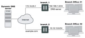
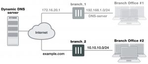
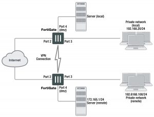
In this scenario, two branch offices each have a FortiGate unit and are connected in a gateway-to-gateway VPN configuration. One FortiGate unit has a domain name (example.com) with a dynamic IP address. See branch_2 in the figure below.

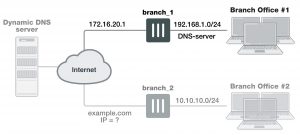
Whenever the branch_2 unit connects to the Internet (and possibly also at predefined intervals set by the ISP), the ISP may assign a different IP address to the FortiGate unit. The unit has its domain name registered with a dynamic DNS service. The branch_2 unit checks in with the DDNS server on a regular basis, and that server provides the DNS information for the domain name, updating the IP address from time to time. Remote peers have to locate the branch_2 FortiGate unit through a DNS lookup each time to ensure the address they get is current and correct.


Example dynamic DNS configuration

dynamic-dns-configuration

When a remote peer (such as the branch_1 FortiGate unit above) initiates a connection to example.com, the local DNS server looks up and returns the IP address that matches the domain name example.com. The remote peer uses the retrieved IP address to establish a VPN connection with the branch_2 FortiGate unit.


Assumptions

  • You have administrator access to both FortiGate units.
  • Both FortiGate units have interfaces named wan1 and internal. (If not, you can use the alias feature to assign these labels as “nicknames” to other interfaces to follow this example.)
  • Both FortiGate units have the most recent firmware installed, have been configured for their networks, and are currently passing normal network traffic.
  • The branch_2 FortiGate unit has its wan1 interface defined as a dynamic DNS interface with the domain name of example.com.
  • A basic gateway-to-gateway configuration is in place (see Gateway-to-gateway configurations on page 1655) except one of the FortiGate units has a static domain name and a dynamic IP address instead of a static IP address.
  • The FortiGate unit with the domain name is subscribed to one of the supported dynamic DNS services. Contact one of the services to set up an account. For more information and instructions about how to configure the FortiGate unit to push its dynamic IP address to a dynamic DNS server, see the System Administration handbook chapter.


General configuration steps

When a FortiGate unit receives a connection request from a remote VPN peer, it uses IPsec Phase 1 parameters to establish a secure connection and authenticate the VPN peer. Then, if the security policy permits the connection, the FortiGate unit establishes the tunnel using IPsec Phase 2 parameters and applies the security policy. Key management, authentication, and security services are negotiated dynamically through the IKE protocol.


To support these functions, the following general configuration steps must be performed:

  • Configure the branch_2 FortiGate unit with the dynamic IP address. This unit uses a Local ID string instead of an IP address to identify itself to the remote peer. See General configuration steps below.
  • General configuration steps
  • General configuration steps
  • Configure the fixed-address VPN peer. To initiate a VPN tunnel with the dynamically-addressed peer, this unit must first retrieve the IP address for the domain from the dynamic DNS service. See General configuration steps on page 1691.
  • General configuration steps
  • General configuration steps


Configure the dynamically-addressed VPN peer

It is assumed that this FortiGate unit (branch_2) has already had its public facing interface, for example the wan1, configured with the proper dynamic DNS configuration.


Configure branch_2, the dynamic address side

dynamic-address-side

Configuring the dynamically-addressed VPN peer includes:

  • Configuring branch_2 VPN tunnel settings
  • Configuring branch_2 security policies


Configuring branch_2 VPN tunnel settings

Define the Phase 1 parameters needed to establish a secure connection with the remote peer. See Phase 1 parameters on page 1624. During this procedure you need to choose if you will be using route-based or policy- based VPNs.


To configure branch_2 VPN tunnel settings

1. Go to VPN > IPsec Tunnels and create the new custom tunnel or edit an existing tunnel.

2. Edit the Phase 1 Proposal (if it is not available, you may need to click the Convert to Custom Tunnel button).

3. Enter the following information:

Name                                           Enter branch_2, a name to identify the VPN tunnel. This name appears in Phase 2 configurations, security policies, and the VPN monitor.

Remote Gateway                               Select Static IP Address.

The remote peer this FortiGate is connecting to has a static IP public address.

If the remote interface is PPPoE do not select Retrieve default gateway from server.

IP Address                                 Enter 172.16.20.1. The IP address of the public interface to the remote peer.

Enter 172.16.20.1

The IP address of the public interface to the remote peer.

Select Aggressive.

4. Select Advanced and complete the following:

Local ID                                              Enter example.com.

A character string used by the branch_2 FortiGate unit to identify itself to the remote peer.

This value must be identical to the value in the This peer ID field of the Phase 1 remote gateway configuration on the branch_1 remote peer. See Configure the dynamically- addressed VPN peer on page 1692.

5. Open the Phase 2 Selectors panel.

Define the Phase 2 parameters needed to create a VPN tunnel with the remote peer. For details on Phase 2, see

Phase 2 parameters on page 1642.

6. Enter the following information and select OK.

Name                                                  Enter branch_2_phase2.

A name to identify this Phase 2 configuration.

Phase 1                                              Select branch_2.

The name of the Phase 1 configuration that you defined earlier.


Configuring branch_2 security policies

Define security policies to permit communications between the private networks through the VPN tunnel. Route- based and policy-based VPNs require different security policies. For detailed information about creating security policies, see Defining VPN security policies on page 1648.

After defining the two address ranges, select one of Creating branch_2 route-based security policies on page 1694 or Creating branch_2 policy-based security policies on page 1696 to configure the appropriate VPN policies.


Define address ranges for branch_2 security policies

Define VPN connection names for the address ranges of the private networks. These addresses are used in the security policies that permit communication between the networks. For more information, see Defining VPN security policies on page 1648.

Define an address name for the IP address and netmask of the private network behind the local FortiGate unit.


To define branch_2 address ranges

1. Go to Policy & Objects > Addresses.

2. Select Create New.

3. Enter the following information, and select OK.

Name                                          Enter branch_2_internal. Enter a meaningful name.

Type                                            Select Subnet.

Subnet / IP Range                             Enter 10.10.10.0/24.

Include the netmask or specify a specific range.

Interface                                     Select internal. The interface that will be handling the traffic from the internal network.

Define an address name for the IP address and netmask of the private network behind the remote peer.

4. Select Create New.

5. Enter the following information, and select OK.

Name                                          Enter branch_1_internal. A meaningful name for the private network at the remote end of the VPN tunnel.

Type                                            Select Subnet.

Subnet / IP Range                             Enter 192.168.1.0/24.

Include the netmask. Optionally you can specify a range

Interface                                             Select any.

The interface that will be handling the remote VPN traffic on this FortiGate unit. If you are unsure, or multiple interfaces may be handling this traffic use any.


Creating branch_2 route-based security policies

Define ACCEPT security policies to permit communication between the branch_2 and branch_1 private networks. Once the route-based policy is configured a routing entry must be configured to route traffic over the VPN interface.

Define a policy to permit the branch_2 local FortiGate unit to initiate a VPN session with the branch_1 VPN peer.


To create route-based security policies

1. Go to Policy & Objects > IPv4 Policy and select Create New.

2. Leave the Policy Type as Firewall and leave the Policy Subtype as Address.

3. Enter the following information, and select OK.


Incoming Interface                           Select internal.

The interface that connects to the private network behind this FortiGate unit.


Source Address                                Select branch_2_internal.

Select the address name for the private network behind this FortiGate unit.


Outgoing Interface                   Select branch_2. The VPN Tunnel (IPsec Interface).

Destination Address                         Select branch_1_internal.

The address name the private network behind the remote peer.

Action                                         Select ACCEPT.

Enable NAT                                Disable.

Comments                                  Route-based: Initiate a branch_2 to branch_1 VPN tunnel.


Define a policy to permit the branch_1 remote VPN peer to initiate VPN sessions.

4. Select Create New.

5. Leave the Policy Type as Firewall and leave the Policy Subtype as Address.

6. Enter the following information, and select OK.

Incoming Interface                   Select branch_2. The VPN Tunnel (IPsec Interface).

Source Address                        Select branch_1_internal. The address name for the private network behind the remote peer.

Outgoing Interface                   Select internal. The interface connecting the private network behind this FortiGate unit.

Destination Address                 Select branch_2_internal. The address name for the private network behind this FortiGate unit.

Action                                         Select ACCEPT.

Enable NAT                                Disable.

Comments                                  Route-based: Initiate a branch_1 to branch_2 internal VPN tunnel.

7. Optionally configure any other security policy settings you require such as UTM or traffic shaping for this policy.

8. Place these policies in the policy list above any other policies having similar source and destination addresses.

This will ensure VPN traffic is matched against the VPN policies before any other policies.


To create routing entry for VPN interface – CLI

config router static edit 5

set dst 0.0.0.0 0.0.0.0

set dynamic-dateway enable set device wan1

next end

This routing entry must be added in the CLI because the dynamic-gateway option is not available in the web- based manager.


Creating branch_2 policy-based security policies

Define an IPsec policy to permit VPN sessions between the private networks. Define an IPsec policy to permit the VPN sessions between the local branch_2 unit and the remote branch_1 unit.

1. Go to Policy & Objects > IPv4 Policy and select Create New.

2. Enter the following information, and select OK.


Incoming Interface                   Select internal. The interface connecting the private network behind this FortiGate unit.

Source Address                        Select branch_2_internal. The address name for the private network behind this local FortiGate unit.

Outgoing Interface                   Select wan1. The FortiGate unit’s public interface.

Destination Address                 Select branch_1_internal. The address name for the private network behind branch_1, the remote peer.

VPN Tunnel                                Select Use Existing and select branch_2 from the drop-down list. The name of the Phase 1 tunnel.

Select Allow traffic to be initiated from the remote site.

Comments                                  Policy-based: allows traffic in either direction to initiate the VPN tunnel.

3. Optionally configure any other security policy settings you require such as UTM or traffic shaping for this policy.

4. Place these policies in the policy list above any other policies having similar source and destination addresses.

This will ensure VPN traffic is matched against the VPN policies before any other policies.


Configure the fixed-address VPN peer

The fixed-address VPN peer, branch_1, needs to retrieve the IP address from the dynamic DNS service to initiate communication with the dynamically-addressed peer, branch_2. It also depends on the peer ID (local ID) to initiate the VPN tunnel with branch_2.


Configure branch_1, the fixed address side

branch-1

Configuring the fixed-address VPN peer includes:

  • Configuring branch_1 VPN tunnel settings
  • Configuring branch_1 security policies


Configuring branch_1 VPN tunnel settings

Define the Phase 1 parameters needed to establish a secure connection with the remote peer. For more information, see Phase 1 parameters on page 1624.


To configure branch_1 Phase 1 VPN settings

1. Go to VPN > IPsec Tunnels and create the new custom tunnel or edit an existing tunnel.

2. Edit the Phase 1 Proposal (if it is not available, you may need to click the Convert to Custom Tunnel button).

3. Enter the following information and select OK.

Name                                           Enter branch_1. A name to identify the VPN tunnel. This name appears in Phase 2 configurations, security policies and the VPN monitor.

Remote Gateway                       Select Dynamic DNS. The remote peer this FortiGate is connecting to has a dynamic IP address.

Dynamic DNS                            Type the fully qualified domain name of the remote peer (for example, example.com).

Interface                                     Select wan1. The public facing interface on the fixed-address FortiGate unit.

Mode                                           Select Aggressive.

Peer Options                             Select This peer ID, and enter example.com. This option only appears when the mode is set to Aggressive. The identifier of the FortiGate unit with the dynamic address.

4. Define the Phase 2 parameters needed to create a VPN tunnel with the remote peer. See Phase 2 parameters on page 1642. Enter these settings in particular:

Name                                           Enter branch_1_p2. A name to identify this Phase 2 configuration.

Phase 1                                       Select branch_1.

The name of the Phase 1 configuration that you defined for the remote peer. You can select the name of the remote gateway from the Dynamic DNS part of the list.


Configuring branch_1 security policies

The branch_1 FortiGate unit has a fixed IP address and will be connecting to the branch_2 FortiGate unit that has a dynamic IP address and a domain name of example.com. Remember if you are using route-based security policies that you must add a route for the VPN traffic.


Defining address ranges for branch_1 security policies

As with branch_2 previously, branch_1 needs address ranges defined as well. See Defining VPN security policies on page 1648.

1. Go to Policy & Objects > Addresses.

2. Select Create New.

3. Enter the following information, and select OK.

Name                                           Enter branch_2_internal. A meaningful name for the private network behind the branch_2 FortiGate unit.

Type                                            Select Subnet.

Subnet / IP Range                     Enter 10.10.10.0/24. Include the netmask or specify a specific range.

Interface                                     Select internal. This is the interface on this FortiGate unit that will be hand- ling with this traffic.

4. Define an address name for the IP address and netmask of the private network behind the remote peer.

5. Select Create New.

6. Enter the following information, and select OK.

Name                                           Enter branch_1_internal. A meaningful name for the private network behind the branch_1 peer.

Type                                            Select Subnet.

Subnet / IP Range                     Enter 192.168.1.0/24. Include the netmask or specify a specific range.

Interface                                     Select any. The interface on this FortiGate unit that will be handling with this traffic. If you are unsure, or multiple interfaces may be handling this traffic use any.


Creating branch_1 route-based security policies

Define an ACCEPT security policy to permit communications between the source and destination addresses. See Defining VPN security policies on page 1648.

1. Go to Policy & Objects > IPv4 Policy and select Create New.

2. Leave the Policy Type as Firewall and leave the Policy Subtype as Address.

3. Enter the following information, and select OK.

Incoming Interface                   Select internal. The interface that connects to the private network behind the branch_1 FortiGate unit.

Source Address                        Select branch_1_internal. The address name that you defined for the private network behind this FortiGate unit.

Outgoing Interface                   Select branch_1. The VPN Tunnel (IPsec Interface) you configured earlier.

Destination Address                 Select branch_2_internal. The address name that you defined for the private network behind the branch_2 peer.

Action                                         Select ACCEPT.

Enable NAT                                Disable

Comments                                  Internal -> branch2

To permit the remote client to initiate communication, you need to define a security policy for communication in that direction.

4. Select Create New.

5. Leave the Policy Type as Firewall and leave the Policy Subtype as Address.

6. Enter the following information, and select OK.

Incoming Interface                   Select branch_1. The VPN Tunnel (IPsec Interface) you configured earlier.

Source Address                        Select branch_2_internal. The address name that you defined for the private network behind the branch_2 remote peer.

Outgoing Interface                   Select internal. The interface that connects to the private network behind this FortiGate unit.

Destination Address                 Select branch_1_internal. The address name that you defined for the private network behind this FortiGate unit.

Action                                         Select ACCEPT.

Enable NAT                                Disable

Comments                                  branch_2 -> Internal


Creating branch_1 policy-based security policies

A policy-based security policy allows you the flexibility to allow inbound or outbound traffic or both through this single policy.

This policy-based IPsec VPN security policy allows both inbound and outbound traffic

1. Go to Policy & Objects > IPv4 Policy and select Create New.

2. Enter the following information, and select OK.

Incoming Interface                   Select internal. The interface that connects to the private network behind this FortiGate unit.

Source Address                        Select branch_1_internal. The address name that you defined for the private network behind this FortiGate unit.

Outgoing Interface                   Select wan1. The FortiGate unit’s public interface.

Destination Address                 Select branch_2_internal. The address name that you defined for the private network behind the remote peer.

VPN Tunnel                                        Select Use Existing and select branch_1 from the drop-down list.

Select Allow traffic to be initiated from the remote site to enable traffic from the remote network to initiate the tunnel.

3. Place this security policy in the policy list above any other policies having similar source and destination addresses.


Testing

Once both ends are configured, you can test the VPN tunnel.


To test the VPN initiated by branch_2

1. On branch_2, go to Monitor > IPsec Monitor.

All IPsec VPN tunnels will be listed on this page, no matter if they are connected or disconnected.

2. Select the tunnel listed for branch_2, and select the status column for that entry.

The status will say Bring Up and remote port, incoming and outgoing data will all be zero. This indicates an inactive tunnel. When you select Bring Up, the FortiGate will try to set up a VPN session over this tunnel. If it is successful, Bring Up will change to Active, and the arrow icon will change to a green up arrow icon.

3. If this does not create a VPN tunnel with increasing values for incoming and outgoing data, you need to start troubleshooting:


To test the VPN initiated by branch_1

1. On branch_1, go to Monitor > IPsec Monitor.

2. Select the tunnel listed for branch_1, and select the status column.

The difference between branch_2 and branch_1 at this point is that the tunnel entry for branch-1 will not have a remote gateway IP address. It will be resolved when the VPN tunnel is started.

3. If this does not create a VPN tunnel with increasing values for incoming and outgoing data, you need to start troubleshooting.

Some troubleshooting ideas include:

  • If there was no entry for the tunnel on the monitor page, check the Auto Key (IKE) page to verify the Phase 1 and Phase 2 entries exist.
  • Check the security policy or policies, and ensure there is an outgoing policy as a minimum.
  • Check that you entered a local ID in the Phase 1 configuration, and that branch_1 has the same local ID.
  • Ensure the local DNS server has an up-to-date DNS entry for exmaple.com. For more information, see Troubleshooting on page 1826.


Having trouble configuring your Fortinet hardware or have some questions you need answered? Check Out The Fortinet Guru Youtube Channel! Want someone else to deal with it for you? Get some consulting from Fortinet GURU!

Gateway-to-gateway configurations

Gateway-togateway configurations

This section explains how to set up a basic gateway-to-gateway (site-to-site) IPsec VPN. The following topics are included in this section:

  • Configuration overview
  • General configuration steps
  • Configuring the two VPN peers
  • How to work with overlapping subnets
  • Testing


Configuration overview

In a gateway-to-gateway configuration, two FortiGate units create a VPN tunnel between two separate private networks. All traffic between the two networks is encrypted and protected by FortiGate security policies.


Example gateway-to-gateway configuration

gateway-to-gateway-configurations


In some cases, computers on the private network behind one VPN peer may (by co-incidence) have IP addresses that are already used by computers on the network behind the other VPN peer. In this type of situation (ambiguous routing), conflicts may occur in one or both of the FortiGate routing tables and traffic destined for the remote network through the tunnel may not be sent. To resolve issues related to ambiguous routing, see Configuration overview on page 1655.

In other cases, computers on the private network behind one VPN peer may obtain IP addresses from a local DHCP server. However, unless the local and remote networks use different private network address spaces, unintended ambiguous routing and/or IP-address overlap issues may arise. For a discussion of the related issues, see FortiGate dialup-client configurations on page 1716.

You can set up a fully meshed or partially meshed configuration (see below).


Fully meshed configuration

fully-meshed-configuration


In a fully meshed network, all VPN peers are connected to each other, with one hop between peers. This topology is the most fault-tolerant: if one peer goes down, the rest of the network is not affected. This topology is difficult

to scale because it requires connections between all peers. In addition, unnecessary communication can occur between peers. Best practices dictates a hub-and-spoke configuration instead (see Hub-and-spoke configurations on page 1671).


Partially meshed configuration

partially-meshed


A partially meshed network is similar to a fully meshed network, but instead of having tunnels between all peers, tunnels are only configured between peers that communicate with each other regularly.


General configuration steps

The FortiGate units at both ends of the tunnel must be operating in NAT mode and have static public IP addresses.

When a FortiGate unit receives a connection request from a remote VPN peer, it uses IPsec Phase 1 parameters to establish a secure connection and authenticate that VPN peer. Then, if the security policy permits the connection, the FortiGate unit establishes the tunnel using IPsec Phase 2 parameters and applies the IPsec security policy. Key management, authentication, and security services are negotiated dynamically through the IKE protocol.

To support these functions, the following general configuration steps must be performed by both FortiGate units:

  • Define the Phase 1 parameters that the FortiGate unit needs to authenticate the remote peer and establish a secure connection.
  • Define the Phase 2 parameters that the FortiGate unit needs to create a VPN tunnel with the remote peer.
  • Create security policies to control the permitted services and permitted direction of traffic between the IP source and destination addresses.


Configuring the two VPN peers

Configure the VPN peers as follows. Each step is required, but these are general steps. For more detailed information on each step follow the cross references. See Phase 1 parameters on page 1624. All steps are required. Cross references point to required information that is repeated. No steps are optional.


Having trouble configuring your Fortinet hardware or have some questions you need answered? Check Out The Fortinet Guru Youtube Channel! Want someone else to deal with it for you? Get some consulting from Fortinet GURU!

Defining VPN security policies

Defining VPN security policies

This section explains how to specify the source and destination IP addresses of traffic transmitted through an IPsec VPN, and how to define appropriate security policies. The following topics are included in this section:

  • Defining policy addresses
  • Defining VPN security policies


Defining policy addresses

A VPN tunnel has two end points. These end points may be VPN peers such as two FortiGate gateways. Encrypted packets are transmitted between the end points. At each end of the VPN tunnel, a VPN peer intercepts encrypted packets, decrypts the packets, and forwards the decrypted IP packets to the intended destination.

You need to define firewall addresses for the private networks behind each peer. You will use these addresses as the source or destination address depending on the security policy.


Example topology for the following policies

vpn-topology-example


In general:

  • In a gateway-to-gateway, hub-and-spoke, dynamic DNS, redundant-tunnel, or transparent configuration, you need to define a policy address for the private IP address of the network behind the remote VPN peer (for example,192.168.10.0/255.255.255.0 or 192.168.10.0/24).
  • In a peer-to-peer configuration, you need to define a policy address for the private IP address of a server or host behind the remote VPN peer (for example, 172.16.5.1/255.255.255.255 or 172.16.5.1/32 or 172.16.5.1).


For a FortiGate dialup server in a dialup-client or Internet-browsing configuration:

  • If you are not using VIP addresses, or if the FortiGate dialup server assigns VIP addresses to FortiClient dialup clients through FortiGate DHCP relay, select the predefined destination address “all” in the security policy to refer to the dialup clients
  • If you assign VIP addresses to FortiClient dialup clients manually, you need to define a policy address for the VIP address assigned to the dialup client (for example, 10.254.254.1/32), or a subnet address from which the VIP addresses are assigned (for example, 10.254.254.0/24 or 10.254.254.0/255.255.255.0).
  • For a FortiGate dialup client in a dialup-client or Internet-browsing configuration, you need to define a policy address for the private IP address of a host, server, or network behind the FortiGate dialup server.


To define a security IP address

1. Go to Policy & Objects > Addresses and select Create New.

2. In the Name field, type a descriptive name that represents the network, server(s), or host(s).

3. In Type, select Subnet.

4. In the Subnet/IP Range field, type the corresponding IP address and subnet mask.

For a subnet you could use the format 172.16.5.0/24 or its equivalent 172.16.5.0/255.255.255.0. For a server or host it would likely be 172.16.5.1/32. Alternately you can use an IP address range such as 192.168.10.[80-100] or 192.168.10.80-192.168.10.100.

5. Select OK.


Defining VPN security policies

Security policies allow IP traffic to pass between interfaces on a FortiGate unit. You can limit communication to particular traffic by specifying source address and destination addresses. Then only traffic from those addresses will be allowed.

Policy-based and route-based VPNs require different security policies.

  • A policy-based VPN requires an IPsec security policy. You specify the interface to the private network, the interface to the remote peer and the VPN tunnel. A single policy can enable traffic inbound, outbound, or in both directions.
  • A route-based VPN requires an Accept security policy for each direction. As source and destination interfaces, you specify the interface to the private network and the virtual IPsec interface (Phase 1 configuration) of the VPN. The IPsec interface is the destination interface for the outbound policy and the source interface for the inbound policy. One security policy must be configured for each direction of each VPN interface.


There are examples of security policies for both policy-based and route-based VPNs throughout this guide. See Dynamic DNS configuration on page 1688.

If the security policy, which grants the VPN Connection is limited to certain services, DHCP must be included, otherwise the client won’t be able to retrieve a lease from the FortiGate’s (IPsec) DHCP server, because the DHCP Request (coming out of the tun- nel) will be blocked.


Defining an IPsec security policy for a policy-based VPN

An IPsec security policy enables the transmission and reception of encrypted packets, specifies the permitted direction of VPN traffic, and selects the VPN tunnel. In most cases, a single policy is needed to control both inbound and outbound IP traffic through a VPN tunnel.


Allow traffic to be initiated from the remote site

In addition to these operations, security policies specify which IP addresses can initiate a tunnel. by default, traffic from the local private network initiates the tunnel. When the Allow traffic to be initiated form the remote site option is selected, traffic from a dialup client or computers on the remote network initiates the tunnel. Both can be enabled at the same time for bi-directional initiation of the tunnel.


Outbound and inbound NAT

When a FortiGate unit operates in NAT mode, you can also enable inbound or outbound NAT. Outbound NAT may be performed on outbound encrypted packets, or on IP packets before they are sent through the tunnel.

Inbound NAT is performed on IP packets emerging from the tunnel. By default, these options are not selected in security policies.

When used in conjunction with the natip CLI attribute (see the “config firewall” chapter of the FortiGate CLI Reference), outbound NAT enables you to change the source addresses of IP packets before they go into the tunnel. This feature is often used to resolve ambiguous routing when two or more of the private networks making up a VPN have the same or overlapping IP addresses. .

When inbound NAT is enabled, inbound encrypted packets are intercepted and decrypted, and the source IP addresses of the decrypted packets are translated into the IP address of the FortiGate interface to the local private network before they are routed to the private network. If the computers on the local private network can communicate only with devices on the local private network (that is, the FortiGate interface to the private network is not the default gateway) and the remote client (or remote private network) does not have an IP address in the same network address space as the local private network, enable inbound NAT.


Source and destination addresses

Most security policies control outbound IP traffic. A VPN outbound policy usually has a source address originating on the private network behind the local FortiGate unit, and a destination address belonging to a dialup VPN client or a network behind the remote VPN peer. The source address that you choose for the security policy identifies from where outbound cleartext IP packets may originate, and also defines the local IP address or addresses that a remote server or client will be allowed to access through the VPN tunnel. The destination address that you choose identifies where IP packets must be forwarded after they are decrypted at the far end of the tunnel, and determines the IP address or addresses that the local network will be able to access at the far end of the tunnel.


Enabling other policy features

You can fine-tune a policy for services such as HTTP, FTP, and POP3; enable logging, traffic shaping, antivirus protection, web filtering, email filtering, file transfer, and email services throughout the VPN; and optionally allow connections according to a predefined schedule.

As an option, differentiated services (diffserv or DSCP) can be enabled in the security policy through CLI commands. For more information on this feature, see the Traffic Shaping handbook chapter, or the “firewall” chapter of the FortiGate CLI Reference.

When a remote server or client attempts to connect to the private network behind a FortiGate gateway, the security policy intercepts the connection attempt and starts the VPN tunnel. The FortiGate unit uses the remote gateway specified in its Phase 1 tunnel configuration to reply to the remote peer. When the remote peer receives a reply, it checks its own security policy, including the tunnel configuration, to determine which communications are permitted. As long as one or more services are allowed through the VPN tunnel, the two peers begin to negotiate the tunnel. To follow this negotiation in the web-based manager, go to Monitor > IPsec Monitor. There you will find a list of the VPN tunnels, their status, and the data flow both incoming and outgoing.


Before you begin

Before you define the IPsec policy, you must:

  • Define the IP source and destination addresses. See Defining VPN security policies on page 1650.
  • Specify the Phase 1 authentication parameters. See Phase 1 parameters on page 1624.
  • Specify the Phase 2 parameters. See Phase 2 parameters on page 1642.


To define an IPsec security policy

1. Go to Policy & Objects > IPv4 Policy.

2. Select Create New and set the following options:

Incoming Interface                   Select the local interface to the internal (private) network.

Source Address                        Select the name that corresponds to the local network, server(s), or host(s) from which IP packets may originate.

Outgoing Interface                   Select the local interface to the external (public) network.

Destination Address                 Select the name that corresponds to the remote network, server(s), or host (s) to which IP packets may be delivered.

Schedule                                    Keep the default setting (always) unless changes are needed to meet spe- cific requirements.

Service                                       Keep the default setting (ANY) unless changes are needed to meet your specific requirements.

VPN Tunnel                                Select Use Existing and select the tunnel from the drop-down list.

Allo traffic to be initiated from the remote site

Select if traffic from the remote network will be allowed to initiate the tun- nel.

3. You may enable UTM features, and/or event logging, or select advanced settings to authenticate a user group, or shape traffic. For more information, see the Firewall handbook chapter.

4. Select OK.

5. Place the policy in the policy list above any other policies having similar source and destination addresses.


Defining multiple IPsec policies for the same tunnel

You must define at least one IPsec policy for each VPN tunnel. If the same remote server or client requires access to more than one network behind a local FortiGate unit, the FortiGate unit must be configured with an IPsec policy for each network. Multiple policies may be required to configure redundant connections to a remote destination or control access to different services at different times.

To ensure a secure connection, the FortiGate unit must evaluate IPSEC policies before ACCEPT and DENY security policies. Because the FortiGate unit reads policies starting at the top of the list, you must move all IPsec policies to the top of the list. When you define multiple IPsec policies for the same tunnel, you must reorder the IPsec policies that apply to the tunnel so that specific constraints can be evaluated before general constraints.

Adding multiple IPsec policies for the same VPN tunnel can cause conflicts if the policies specify similar source and destination addresses but have different settings for the same service. When policies overlap in this manner, the system may apply the wrong IPsec policy or the tunnel may fail.

For example, if you create two equivalent IPsec policies for two different tunnels, it does not matter which one comes first in the list of IPsec policies — the system will select the correct policy based on the specified source and destination addresses. If you create two different IPsec policies for the same tunnel (that is, the two policies treat traffic differently depending on the nature of the connection request), you might have to reorder the IPsec policies to ensure that the system selects the correct IPsec policy. Reordering is especially important when the source and destination addresses in both policies are similar (for example, if one policy specifies a subset of the IP addresses in another policy). In this case, place the IPsec policy having the most specific constraints at the top of the list so that it can be evaluated first.


Defining security policies for a route-based VPN

When you define a route-based VPN, you create a virtual IPsec interface on the physical interface that connects to the remote peer. You create ordinary Accept security policies to enable traffic between the IPsec interface and the interface that connects to the private network. This makes configuration simpler than for policy-based VPNs, which require IPsec security policies.


To define security policies for a route-based VPN

1. Go to Policy & Objects > IPv4 Policy.

2. Select Create New and leave the Policy Type as Firewall, and the Policy Subtype as Address.

3. Define an ACCEPT security policy to permit communications between the local private network and the private network behind the remote peer. Enter these settings in particular:

Incoming Interface                   Select the interface that connects to the private network behind this FortiGate unit.

Source Address                        Select the address name that you defined for the private network behind this FortiGate unit.

Outgoing Interface                   Select the IPsec Interface you configured.

Destination Address                 Select the address name that you defined for the private network behind the remote peer.

Action                                         Select ACCEPT.

Enable NAT                                Disable.


To permit the remote client to initiate communication, you need to define a security policy for communication in that direction.

4. Select Create New and leave the Policy Type as Firewall, and the Policy Subtype as Address

5. Enter these settings in particular:

Incoming Interface                   Select the IPsec Interface you configured.

Source Address                        Select the address name that you defined for the private network behind the remote peer.

Outgoing Interface                   Select the interface that connects to the private network behind this FortiGate unit.

Destination Address                 Select the address name that you defined for the private network behind this FortiGate unit.

Action                                         Select ACCEPT.

Enable NAT                                Disable.


Having trouble configuring your Fortinet hardware or have some questions you need answered? Check Out The Fortinet Guru Youtube Channel! Want someone else to deal with it for you? Get some consulting from Fortinet GURU!