Category Archives: FortiOS

Monitoring VPN connections

This section provides some general logging and monitoring procedures for VPNs. The following topics are included in this section:

  • Monitoring VPN connections
  • Logging VPN events


Monitoring VPN connections

You can use the monitor to view activity on IPsec VPN tunnels and to start or stop those tunnels. The display provides a list of addresses, proxy IDs, and timeout information for all active tunnels.


Monitoring connections to remote peers

The list of tunnels provides information about VPN connections to remote peers that have static IP addresses or domain names. You can use this list to view status and IP addressing information for each tunnel configuration. You can also start and stop individual tunnels from the list.

To view the list of static-IP and dynamic-DNS tunnels go to Monitor > IPsec Monitor.


Monitoring dialup IPsec connections

The list of dialup tunnels provides information about the status of tunnels that have been established for dialup clients. The list displays the IP addresses of dialup clients and the names of all active tunnels. The number of tunnels shown in the list can change as dialup clients connect and disconnect.

To view the list of dialup tunnels go to Monitor > IPsec Monitor.

If you take down an active tunnel while a dialup client such as FortiClient is still connected, FortiClient will continue to show the tunnel connected and idle. The dialup client must disconnect before another tunnel can be initiated.


The list of dialup tunnels displays the following statistics:

  • The Name column displays the name of the tunnel.
  • The meaning of the value in the Remote gateway column changes, depending on the configuration of the network at the far end:
  • When a FortiClient dialup client establishes a tunnel, the Remote gateway column displays either the public IP address and UDP port of the remote host device (on which the FortiClient Endpoint Security application is installed), or if a NAT device exists in front of the remote host, the Remote gateway column displays the public IP address and UDP port of the remote host.
  • When a FortiGate dialup client establishes a tunnel, the Remote gateway column displays the public IP address and UDP port of the FortiGate dialup client.
  • The Username column displays the peer ID, certificate name, or XAuth user name of the dialup client (if a peer ID, certificate name, or XAuth user name was assigned to the dialup client for authentication purposes).
  • The Timeout column displays the time before the next key exchange. The time is calculated by subtracting the time elapsed since the last key exchange from the keylife.
  • The Proxy ID Source column displays the IP addresses of the hosts, servers, or private networks behind the FortiGate unit. A network range may be displayed if the source address in the security encryption policy was expressed as a range of IP addresses.
  • The meaning of the value in the Proxy ID Destination column changes, depending on the configuration of the network at the far end:
  • When a FortiClient dialup client establishes a tunnel:
  • If VIP addresses are not used and the remote host connects to the Internet directly, the Proxy ID Destination field displays the public IP address of the Network Interface Card (NIC) in the remote host.
  • If VIP addresses are not used and the remote host is behind a NAT device, the Proxy ID Destination field displays the private IP address of the NIC in the remote host.
  • If VIP addresses were configured (manually or through FortiGate DHCP relay), the Proxy ID Destination field displays either the VIP address belonging to a FortiClient dialup client, or a subnet address from which VIP addresses were assigned.
  • When a FortiGate dialup client establishes a tunnel, the Proxy ID Destination field displays the IP address of the remote private network.

Having trouble configuring your Fortinet hardware or have some questions you need answered? Check Out The Fortinet Guru Youtube Channel! Want someone else to deal with it for you? Get some consulting from Fortinet GURU!

IPsec Auto-Discovery VPN (ADVPN)

IPsec Auto-Discovery VPN (ADVPN)

Consider a company that wants to provide direct secure (IPsec) connections between all of its offices in New York, Chicago, Greenwich, London, Paris, Frankfurt, Tokyo, Shanghai, and Hong Kong.

A straightforward solution is to create a full mesh of connections such that every site has eight IPsec configurations, one for each of the other sites. If there were ninety sites, that could still be done but now the configuration is becoming tedious, since every time a new site is added, N-1 other sites have to have their configuration updated.

An efficient and secure alternative is IPsec Auto-Discovery VPN (ADVPN), which allows a minimum amount of configuration per site but still allows direct IPsec connections to be made between every site. RFC 7018 essentially describes this problem, along with some requirements for candidate solutions.

The ADVPN solution involves partitioning the sites into spokes and hubs such that a spoke has to have enough IPsec configuration to enable it to connect to at least one hub. A hub does not have specific configuration for each spoke, so the amount of configuration does not grow with the number of spokes that are connected to that hub. A hub to hub connection would typically involve both hubs having configuration for each other.

So, one possible partition for the original nine sites would be that Chicago and Greenwich would be spokes for the New York hub, Paris and Frankfurt would be spokes for the London hub, and Tokyo and Hong Kong would be spokes for the Shanghai hub:

ipsec-auto-discovery


Once a spoke has established a connection to its hub then initially IPsec traffic to another site transits via one or more hubs. For example, traffic from Chicago to Hong Kong would transit via the New York and Shanghai hubs. This transit traffic then triggers an attempt to create a more direct connection.


In FortiOS:

  • Direct connections are only created between the two endpoints that want to exchange traffic (e.g. Chicago and Hong Kong); we do not create intermediate connections  say Chicago to Shanghai, or New York to Hong Kong) as a side-effect.
  • Learning the peer subnets is done via a dynamic routing protocol running over the IPsec connections.
  • Negotiation of the direct connections is done via IKE.
  • Both PSK and certificate authentication is supported.


Example ADVPN configuration

Since dynamic routing with IPsec under FortiOS requires that an interface have an IP address, then for every site a unique IP address from some unused range is allocated. For example we’ll assume that 10.100.0.0/16 is unused and so assign the IP addresses:

  • Chicago 10.100.0.4
  • Greenwich 10.100.0.5
  • New York 10.100.0.1
  • London 10.100.0.2
  • Shanghai 10.100.0.3
  • Paris 10.100.0.6
  • Frankfurt 10.100.0.7
  • Hong Kong 10.100.0.8
  • Tokyo 10.100.0.9

We’ll assume that each site has one or more subnets that it protects that it wants to make available to the peers. For the purposes of exposition we’ll assume there is only one subnet per site and they are allocated as:

  • Chicago 10.0.4.0/16
  • Greenwich 10.0.5.0/24
  • New York 10.0.1.0/24
  • London 10.0.2.0/24
  • Shanghai 10.0.3.0/24
  • Paris 10.0.6.0/24
  • Frankfurt 10.0.7.0/24
  • Hong Kong 10.0.8.0/24
  • Tokyo 10.0.9.0/24

Our example network topology now looks like this:

greenwich


The configuraton in Chicago would be as follows:


config vpn ipsec phase1-interface edit “New York”

set type static

set interface wan1

set remote-gw <New-York-IP-address>

set psk <New-York-PSK>

set auto-discovery-receiver enable next

end


The attribute auto-discovery-receiver indicates that this IPsec tunnel wishes to participate in an auto- discovery VPN. The IPsec interface would then have its IP assigned according to the Chicago address:

config system interface edit “New York”

set ip 10.100.0.4/32

set remote-ip 10.100.0.1 next

end


RIP (for simplicity, you could use OSPF or BGP) is then configured to run on the IPsec interface and on the Chicago subnet (you could use redistribute connected, but we’ll allow for the fact that there may be other subnets learned from another router on the 10.0.4.0/24 subnet):

config router rip

edit 1

set prefix 10.100.0.0/16 next

edit 2

set prefix 10.0.4.0/24 next

end


Other than the firewall policy and a minimal phase 2 configuration, this concludes the configuration for Chicago.


Each spoke would have a similar configuration.

The New York hub would have a dynamic phase 1 for its spoke connections, and two static phase 1s for its connections to the other hubs:

config vpn ipsec phase1-interface edit “Spokes”

set type dynamic set interface wan1

set psk <New-York-PSK>

set auto-discovery-sender enable set auto-discovery-psk enable

set add-route disable next

edit “London”

set type static

set interface wan1

set psk <New-York-London-PSK>

set auto-discovery-forwarder enable next

edit “Shanghai”

set type static

set interface wan1

set psk <New-York-Shanghai-PSK>

set auto-discovery-forwarder enable next

end


The ‘Spokes’ connection has set auto-discovery-sender enable to indicate that when IPsec traffic transits the hub it should optionally generate a message to the initiator of the traffic to indicate that it could perhaps establish a more direct connection. The set add-route disable ensures that IKE does not automatically add a route back over the spoke and instead leaves routing to a separately configured routing protocol.

The two inter-hub connections have set auto-discovery-forwarder enable to indicate that these connections can participate in the auto-discovery process. The interface IP addresses are assigned:

config system interface edit “Spokes”

set ip 10.100.0.1/32

set remote-ip 10.100.0.254 next

edit “London”

set ip 10.100.0.1/32

set remote-ip 10.100.0.2 next

edit “London”

set ip 10.100.0.1/32

set remote-ip 10.100.0.3 next

end


Following this, RIP is enabled on the relevant interfaces:

config router rip edit 1

set prefix 10.100.0.0/16 next

edit 2

set prefix 10.0.1.0/24 next

end


A similar configuration would be used on the other two hubs.


Traffic flow and tunnel connection

With the configuration in place at all spokes and hubs, assuming all the spokes are connected to a hub, then Chicago would learn (via RIP) that the route to the Hong Kong subnet 10.0.8.0/24 is via its “New York” interface. If a device on the Chicago protected subnet (say 10.0.4.45) attempted to send traffic to the Hong Kong proected subnet (say 10.0.8.13) then it should flow over the New York interface to New York, which should then transmit it over the Shanghai tunnel to Shanghai, which should then send it over the dynamically negotiated Hong Kong tunnel to Hong Kong.

At the point when the traffic transits New York it should notice that the Chicago Spoke tunnel and the Shanghai tunnel have auto-discovery enabled, causing the New York hub to send a message via IKE to Chicago informing it that it may want to try and negotiate a direct connection for traffic from 10.0.4.45 to 10.0.8.13.

On receipt of this message, IKE on Chicago creates the (FortiOS-specific) IKE INFORMATIONAL SHORTCUT- QUERY message which contains the Chicago public IP address, the source IP of the traffic (10.0.4.45), the desired destination IP (10.0.8.13), and the PSK that should be used to secure any direct tunnel (if certificates are confgured, it is assumed that they all share the same CA and so no additional authentication information is required). This message is sent via IKE to New York since routing indicates that New York is the best route to 10.0.8.13.

On receipt of the IKE INFORMATIONAL query, New York checks its routing table to see who owns 10.0.8.13. It finds that 10.0.8.13 should be routed via Shanghai, and since Shanghai is marked as an auto-discovery-forwarder then the query is forwarded.

Shanghai repeats the process, finds that 10.0.8.13 should be routed via its Hong Kong Spoke and so sends it to Hong Kong. Hong Kong checks 10.0.8.13, finds that it owns the subnet, so it remembers the Chicago public IP address (and PSK) and creates an IKE INFORMATIONAL reply message containing its external IP address. To work out where to send the IKE message, the FortiGate does a routing lookup for the original source IP (10.0.4.45), determines that the message should be routed via its Shanghai tunnel and so sends the reply back to Shanghai. The reply then makes its way back to Chicago following the reverse of the path that it used to arrive at Hong Kong.

When the reply makes it back to the Chicago initator then it now knows the IP address of the Hong Kong device. Chicago now creates a new dynamic tunnel with the remote gateway as the Hong Kong public IP address and initiates an IKE negotiation (the dynamic tunnel nameis auto-generated from the tunnel over which it performed the query; in this case it would be called ‘New York_0’).

This negotiation should succeed since Hong Kong is set up to expect an attempted negotiation from the Chicago public IP address. Once the negotiation succeeds, RIP will start to run on the newly created tunnels at Chicago and Hong Kong. This will update the routing on Chicago (and Hong Kong) so that the prefered route to 10.0.8.0 (10.0.4.0) is via the newly created tunnel rather than via the connection to New York (Shanghai).


Notes about ADVPN in FortiOS

  • Auto-discovery is only supported by IKEv1.
  • All Spokes must have an IP address that is routable from any other spoke; devices behind NAT are not currently supported.
  • The feature requires the use of a dynamic routing protocol. There is no support for IKE handling routing.
  • RIP is not a very scalable routing protocol. When there are more than a few spokes it would be advisable to use route summarization to avoid huge RIP updates. Better yet, use BGP instead of RIP.
  • It is assumed that spokes will not be used to transit other spoke traffic, for example: traffic from Chicago to Tokyo would not transit an existing Chicago to Hong Kong tunnel even though that has a shorter hop count than a route via New York and Shanghai.
  • There is no facility to allow you to filter which traffic that transits the hub should trigger the message sent to the initiator suggesting it create a direct connection. Currently any and all traffic will trigger it.

Having trouble configuring your Fortinet hardware or have some questions you need answered? Check Out The Fortinet Guru Youtube Channel! Want someone else to deal with it for you? Get some consulting from Fortinet GURU!

BGP over dynamic IPsec

BGP over dynamic IPsec

This example shows how to create a dynamic IPsec VPN tunnel that allows BGP.


Configuring IPsec on FortiGate 1

1. Go to Policy & Objects > Addresses and select create new Address.

Name                                                Remote_loop_int

Type                                                 Subnet

Subnet/IP Range                             10.10.10.10

Interface                                           any

2. Create an Address Group.

Group Name                                    VPN_DST

Show in Address List                    enable

Members                                          Remote_loop_int all

3. Go to Dashboard and enter the CLI Console widget.

4. Create phase 1:

config vpn ipsec phase1-interface edit Dialup

set type dynamic set interface wan1 set mode aggressive set peertype one

set mode-cfg enable

set proposal 3des-sha1 aes128-sha1 set peerid dial

set assign-ip disable set psksecret

next end

5. Create phase 2:

config vpn ipsec phase2-interface edit dial_p2

set phase1name Dialup

set proposal 3des-sha1 aes128-sha1 set src-addr-type name

set dst-addr-type name set src-name all

set dst-name VPN_DST

next

end


Configuring BGP on FortiGate 1

1. Go to Network > Interfaces and create a Loopback interface.

2. Set IP/Network Mask to 20.20.20.20/255.255.255.255.

3. Go to Dashboard and enter the CLI Console widget.

4. Create a BGP route.

config router bgp set as 100

set router-id 1.1.1.1 config neighbor

edit 10.10.10.10

set ebgp-enforce-multihop enable set remote-as 200

set update-source loop next

end

config redistribute connected set status enable

end

end


Adding policies on FortiGate 1

1. Go to Policy & Objects > IPv4 Policy and create a policy allowing BGP traffic from Dialup to loop interfaces.

2. Go to Policy & Objects > IPv4 Policy and create a policy allowing BGP traffic from loop to Dialup interfaces.


Configuring IPsec on FortiGate 2

1. Go to Dashboard and enter the CLI Console widget.

2. Create phase 1:

config vpn ipsec phase1-interface edit Dialup

set interface wan1 set mode aggressive set mode-cfg enable

set proposal 3des-sha1 aes128-sha1 set localid dial

set remote-gw 172.20.120.22 set assign-ip disable

set psksecret next

end

3. Create phase 2:

config vpn ipsec phase2-interface edit dial_p2

set phase1name Dialup

set proposal 3des-sha1 aes128-sha1 set keepalive enable

next end


BGP over dynamic IPsec


Configuring BGP on FortiGate 2

1. Go to Network > Interfaces and create a Loopback interface.

2. Set IP/Network Mask to 10.10.10.10/255.255.255.255.

3. Go to Dashboard and enter the CLI Console widget.

4. Create a BGP route.

config router bgp set as 200

set router-id 1.1.1.2 config neighbor

edit 20.20.20.20

set ebgp-enforce-multihop enable set remote-as 100

set update-source loop next

end

config redistribute connected set status enable

end

end


Adding policies on FortiGate 2

1. Go to Policy & Objects > IPv4 Policy and create a policy allowing BGP traffic from Dialup to loop interfaces.

2. Go to Policy & Objects > IPv4 Policy and create a policy allowing BGP traffic from loop to Dialup interfaces.


Adding a static route on FortiGate 2

Go to Network > Static Routes and add a route to the remote Loopback interface via Dialup interface.

Destination IP/Mask                       20.20.20.20/255.255.255.255

Device                                              Dialup

Administrative Distance                10


Verifying the tunnel is up

Go to Monitor > IPsec Monitor to verify that the tunnel is Up.


Results

1. From FortiGate 1, go to Monitor > Routing Monitor and verify that routes from FortiGate 2 were successfully advertised to FortiGate 1 via BGP.

2. From FortiGate 1, go to Dashboard.

3. Enter the CLI Console widget and type this command to verify BGP neighbors:

get router info bgp summary

4. From FortiGate 2, go to Monitor > Routing Monitor and verify that routes from FortiGate 1 were successfully advertised to FortiGate 2 via BGP.

5. From FortiGate 2, go to Dashboard.

6. Enter the CLI Console widget and type this command to verify BGP neighbors:

get router info bgp summary


Having trouble configuring your Fortinet hardware or have some questions you need answered? Check Out The Fortinet Guru Youtube Channel! Want someone else to deal with it for you? Get some consulting from Fortinet GURU!

OSPF over dynamic IPsec

OSPF over dynamic IPsec

This example shows how to create a dynamic IPsec VPN tunnel that allows OSPF.


Configuring IPsec on FortiGate 1

1. Go to Dashboard and enter the CLI Console widget

2. Create phase 1:

config vpn ipsec phase1-interface edit “dial-up”

set type dynamic

set interface “wan1” set mode-cfg enable

set proposal 3des-sha1 set add-route disable

set ipv4-start-ip 10.10.101.0 set ipv4-end-ip 10.10.101.255 set psksecret

next end

3. Create phase 2:

config vpn ipsec phase2-interface edit “dial-up-p2”

set phase1name “dial-up”

set proposal 3des-sha1 aes128-sha1 next

end


Configuring OSPF on FortiGate 1

1. Go to Dashboard and enter the CLI Console widget.

2. Create OSPF route.

config router ospf

set router-id 172.20.120.22 config area

edit 0.0.0.0 next

end

config network edit 1

set prefix 10.10.101.0 255.255.255.0 next

end

config redistribute “connected” set status enable

end

config redistribute “static” set status enable

end

end


Adding policies on FortiGate 1

1. Go to Policy & Objects > IPv4 Policy and create a policy allowing OSPF traffic from dialup to port5.

2. Go to Policy & Objects > IPv4 Policy and create a policy allowing OSPF traffic from port5 to dialuinterfaces.


Configuring IPsec on FortiGate 2

1. Go to Dashboard and enter the CLI Console widget

2. Create phase 1:

config vpn ipsec phase1-interface edit “dial-up-client”

set interface “wan1” set mode-cfg enable

set proposal 3des-sha1 set add-route disable

set remote-gw 172.20.120.22 set psksecret

next end

3. Create phase 2:

config vpn ipsec phase2-interface edit “dial-up-client”

set phase1name “dial-up-client”

set proposal 3des-sha1 aes128-sha1 set auto-negotiate enable

next end


Configuring OSPF on FortiGate 2

1. Go to Dashboard and enter the CLI Console widget.

2. Create OSPF route.

config router ospf

set router-id 172.20.120.15 config area

edit 0.0.0.0 next

end

config network edit 1

set prefix 10.10.101.0 255.255.255.0 next

end

config redistribute “connected” set status enable

end

config redistribute “static” set status enable

end

end


Adding policies on FortiGate 2

1. Go to Policy & Objects > IPv4 Policy and create a policy allowing OSPF traffic from dialupclient to port5.

2. Go to Policy & Objects > IPv4 Policy and create a policy allowing OSPF traffic from port5 to dialupclieninterfaces.


Verifying the tunnel is up

Go to Monitor > IPsec Monitor to verify that the tunnel is Up.


Results

1. From FortiGate 1, go to Monitor > Routing Monitor and verify that routes from FortiGate 2 were successfully advertised to FortiGate 1 via OSPF.

2. From FortiGate 1, go to Dashboard. Enter the CLI Console widget and type this command to verify OSPF neighbors:

get router info ospf neighbor

OSPF process 0:

Neighbor     ID Pri State Dead Time    Address Interface

172.20.120.25 1 Full /    –  00:00:34 10.10.101.1 dial-up_0

3. From FortiGate 2, go to Monitor > Routing Monitor and verify that routes from FortiGate 1 were successfully advertised to FortiGate 2 via OSPF.

4. From FortiGate 2, go to Dashboard. Enter the CLI Console widget and type this command to verify OSPF neighbors:

get router info ospf neighbor

OSPF process 0:

Neighbor     ID Pri State Dead Time    Address    Interface

172.20.120.22 1 Full /    –  00:00:30 10.10.101.2 dial-up_client


Having trouble configuring your Fortinet hardware or have some questions you need answered? Check Out The Fortinet Guru Youtube Channel! Want someone else to deal with it for you? Get some consulting from Fortinet GURU!

Redundant OSPF routing over IPsec

Redundant OSPF routing over IPsec

This example sets up redundant secure communication between two remote networks using an Open Shortest Path First (OSPF) VPN connection. In this example, the HQ FortiGate unit will be called FortiGate 1 and the Branch FortiGate unit will be called FortiGate 2.


The steps include:

1. Creating redundant IPsec tunnels on FortiGate 1.

2. Configuring IP addresses and OSPF on FortiGate 1.

3. Configuring firewall addresses on FortiGate 1.

4. Configuring security policies on FortiGate 1.

5. Creating redundant IPsec tunnels for FortiGate 2.

6. Configuring IP addresses and OSPF on FortiGate 2.

7. Configuring firewall addresses on FortiGate 2.

8. Configuring security policies on FortiGate 2.


Creating redundant IPsec tunnels on FortiGate 1

1. Go to VPN > IPsec Tunnels.

2. Select Create New, name the primary tunnel and select Custom VPN Tunnel (No Template).

3. Set the following:

Remote Gateway                          Static IP Address

IP Address                                    FortiGate 2’s wan1 IP

Local Interface                             wan1 (the primary Internet-facing interface)

Preshared Key                            Enter

4. Go to VPN > IPsec Tunnels.

5. Select Create New, name the secondary tunnel and select Custom VPN Tunnel (No Template).

6. Set the following:

Remote Gateway                          Static IP Address

IP Address                                    FortiGate 2’s wan1 IP

Local Interface                             wan2 (the secondary Internet-facing interface)

Preshared Key                            Enter


Configuring IP addresses and OSPF on FortiGate 1

1. Go to Network > Interfaces.

2. Select the arrow for wan1 to expand the list.

3. Edit the primary tunnel interface and create IP addresses.

IP                                                      10.1.1.1

Remote IP                                        10.1.1.2

4. Select the arrow for wan2 to expand the list.

5. Edit the secondary tunnel interface and create IP addresses.

IP                                                      10.2.1.1

Remote IP                                        10.2.1.2

6. Go to Network > OSPF and enter the Router ID for FortiGate 1.

7. Select Create New in the Area section.

8. Add the backbone area of 0.0.0.0.

9. Select Create New in the Networks section.

10. Create the networks and select Area 0.0.0.0 for each one.

11. Select Create New in the Interfaces section.

12. Create primary and secondary tunnel interfaces.

13. Set a Cost of 10 for the primary interface and 100 for the secondary interface.


Configuring firewall addresses on FortiGate 1

1. Go to Policy & Objects > Addresses.

2. Create/Edit the subnets behind FortiGate 1 and FortiGate 2.

3. Create/Edit the primary and secondary interfaces of FortiGate 2.


Configuring security policies on FortiGate 1

1. Go to Policy & Objects > IPv4 Policy.

2. Create the four security policies required for both FortiGate 1’s primary and secondary interfaces to connect to FortiGate 2’s primary and secondary interfaces.

Creating redundant IPsec tunnels on FortiGate 2

1. Go to VPN > IPsec Tunnels.

2. Select Create New, name the primary tunnel and select Custom VPN Tunnel (No Template).

3. Set the following:

Remote Gateway                          Static IP Address

IP Address                                    FortiGate 1’s wan1 IP

Local Interface                             wan1 (the primary Internet-facing interface)

Preshared Key                            Enter

Redundant OSPF routing over IPsec

4. Go to VPN > IPsec Tunnels.

5. Select Create New, name the secondary tunnel and select Custom VPN Tunnel (No Template).

6. Set the following:

Remote Gateway                          Static IP Address

IP Address                                    FortiGate 1’s wan1 IP

Local Interface                             wan2 (the secondary Internet-facing interface)

Preshared Key                            Enter


Configuring IP addresses and OSPF on FortiGate 1

1. Go to Network > Interfaces.

2. Select the arrow for wan1 to expand the list.

3. Edit the primary tunnel interface and create IP addresses.

IP                                                      10.1.1.2

Remote IP                                        10.1.1.1

4. Select the arrow for wan2 to expand the list.

5. Edit the secondary tunnel interface and create IP addresses.

IP                                                      10.2.1.2

Remote IP                                        10.2.1.1

6. Go to Network > OSPF and enter the Router ID for FortiGate 2.

7. Select Create New in the Area section.

8. Add the backbone area of 0.0.0.0.

9. Select Create New in the Networks section.

10. Create the networks and select Area 0.0.0.0 for each one.

11. Select Create New in the Interfaces section.

12. Create primary and secondary tunnel interfaces.

13. Set a Cost of 10 for the primary interface and 100 for the secondary interface.


Configuring firewall addresses on FortiGate 2

1. Go to Policy & Objects > Addresses.

2. Create/Edit the subnets behind FortiGate 1 and FortiGate 2.

3. Create/Edit the primary and secondary interfaces of FortiGate 2.


Configuring security policies on FortiGate 2

1. Go to Policy & Objects > IPv4 Policy.

2. Create the four security policies required for both FortiGate 2’s primary and secondary interfaces to connect to FortiGate 1’s primary and secondary interfaces.


Results

1. Go to Monitor > IPsec Monitor to verify the statuses of both the primary and secondary IPsec VPN tunnels on FortiGate 1 and FortiGate 2.

2. Go to Monitor > Routing Monitor. Monitor to verify the routing table on FortiGate 1 and FortiGate 2. Type OSPF for the Type and select Apply Filter to verify the OSPF route.

3. Verify that traffic flows via the primary tunnel:

  • From a PC1 set to IP:10.20.1.100 behind FortiGate 1, run a tracert to a PC2 set to IP address 10.21.1.00 behind FortiGate 2 and vise versa.
  • From PC1, you should see that the traffic goes through 10.1.1.2 which is the primary tunnel interface IP set on FortiGate 2.
  • From PC2, you should see the traffic goes through 10.1.1.1 which is the primary tunnel interface IP set on FortiGate 1.

4. The VPN network between the two OSPF networks uses the primary VPN connection. Disconnect the wan1 interface and confirm that the secondary tunnel will be used automatically to maintain a secure connection.

5. Verify the IPsec VPN tunnel statuses on FortiGate 1 and FortiGate 2. Both FortiGates should show that primary tunnel is DOWN and secondary tunnel is UP.

6. Go to Monitor > IPsec Monitor to verify the status.

7. Verify the routing table on FortiGate 1 and FortiGate 2.

The secondary OSPF route (with cost = 100) appears on both FortiGate units.

8. Go to Monitor > Routing Monitor. Type OSPF for the Type and select Apply Filter to verify OSPF route.

9. Verify that traffic flows via the secondary tunnel:

  • From a PC1 set to IP:10.20.1.100 behind FortiGate 1, run a tracert to a PC2 set to IP:10.21.1.100 behind FortiGate 2 and vice versa.
  • From PC1, you should see that the traffic goes through 10.2.1.2 which is the secondary tunnel interface IP set on FortiGate 2.
  • From PC2, you should see the traffic goes through 10.2.1.1 which is the secondary tunnel interface IP set on FortiGate 1.


Having trouble configuring your Fortinet hardware or have some questions you need answered? Check Out The Fortinet Guru Youtube Channel! Want someone else to deal with it for you? Get some consulting from Fortinet GURU!

Protecting OSPF with IPsec

Protecting OSPF with IPsec

For enhanced security, OSPF dynamic routing can be carried over IPsec VPN links. The following topics are included in this section:

  • Overview
  • OSPF over IPsec configuration
  • Creating a redundant configuration


Overview

This chapter shows an example of OSPF routing conducted over an IPsec tunnel between two FortiGate units. The network shown below is a single OSPF area. FortiGate_1 is an Area border router that advertises a static route to 10.22.10.0/24 in OSPF. FortiGate_2 advertises its local LAN as an OSPF internal route.


OSPF over an IPsec VPN tunnel

protecting-ospf-over-ipsec

The section Overview describes the configuration with only one IPsec VPN tunnel, tunnel_wan1. Then, the section Overview describes how you can add a second tunnel to provide a redundant backup path. This is shown above as VPN tunnel “tunnel_wan2”.

Only the parts of the configuration concerned with creating the IPsec tunnel and integrating it into the OSPF network are described. It is assumed that security policies are already in place to allow traffic to flow between the interfaces on each FortiGate unit.


OSPF over IPsec configuration

There are several steps to the OSPF-over-IPsec configuration:

  • Configure a route-based IPsec VPN on an external interface. It will connect to a corresponding interface on the other  FortiGate unit. Define the two tunnel-end addresses.
  • Configure a static route to the other FortiGate unit.
  • Configure the tunnel network as part of the OSPF network and define the virtual IPsec interface as an OSPF interface.


This section describes the configuration with only one VPN, tunnel_wan1. The other VPN is added in the section OSPF over IPsec configuration on page 1800.


Configuring the IPsec VPN

A route-based VPN is required. In this chapter, preshared key authentication is shown. Certificate authentication is also possible. Both FortiGate units need this configuration.


To configure Phase 1

1. Define the Phase 1 configuration needed to establish a secure connection with the other FortiGate unit. For more information, see Phase 1 parameters on page 1624.

Enter these settings in particular:

Name                                           Enter a name to identify the VPN tunnel, tunnel_wan1 for example. This becomes the name of the virtual IPsec interface.

Remote Gateway                       Select Static IP Address.

IP Address                                 Enter the IP address of the other FortiGate unit’s public (Port 2) interface.

Local Interface                          Select this FortiGate unit’s public (Port 2) interface.

Mode                                           Select Main (ID Protection).

Authentication Method            Preshared Key

Preshared Key                          Enter the preshared key. It must match the preshared key on the other FortiGate unit.

Advanced                                   Select Advanced.


To assign the tunnel end IP addresses

1. Go to Network > Interfaces, select the virtual IPsec interface that you just created on Port 2 and select Edit.

2. In the IP and Remote IP fields, enter the following tunnel end addresses:


  FortiGate_1 FortiGate_2
IP 10.1.1.1 10.1.1.2
Remote_IP 10.1.1.2 10.1.1.1

These addresses are from a network that is not used for anything else.


To configure Phase 2

1. Enter a name to identify this Phase 2 configuration, twan1_p2, for example.

2. Select the name of the Phase 1 configuration that you defined in Step “OSPF over IPsec configuration” on page 1800, tunnel_wan1 for example.


Configuring static routing


You need to define the route for traffic leaving the external interface.

1. Go to Network > Static Routes, select Create New.

2. Enter the following information.

Destination IP/Mask                 Leave as 0.0.0.0 0.0.0.0.

Device                                         Select the external interface.

Gateway                                     Enter the IP address of the next hop router.


Configuring OSPF

This section does not attempt to explain OSPF router configuration. It focusses on the integration of the IPsec tunnel into the OSPF network. This is accomplished by assigning the tunnel as an OSPF interface, creating an OSPF route to the other FortiGate unit.

This configuration uses loopback interfaces to ease OSPF troubleshooting. The OSPF router ID is set to the loopback interface address.The loopback interface ensures the router is always up. Even though technically the router ID doesn’t have to match a valid IP address on the FortiGate unit, having an IP that matches the router ID makes troubleshooting a lot easier.

The two FortiGate units have slightly different configurations. FortiGate_1 is an AS border router that advertises its static default route. FortiGate_2 advertises its local LAN as an OSPF internal route.

Setting the router ID for each FortiGate unit to the lowest possible value is useful if you want the FortiGate units to be the designated router (DR) for their respective ASes. This is the router that broadcasts the updates for the AS.

Leaving the IP address on the OSPF interface at 0.0.0.0 indicates that all potential routes will be advertised, and it will not be limited to any specific subnet. For example if this IP address was 10.1.0.0, then only routes that match that subnet will be advertised through this interface in OSPF.


FortiGate_1 OSPF configuration

When configuring FortiGate_1 for OSPF, the loopback interface is created, and then you configure OSPF area networks and interfaces.

With the exception of creating the loopback interface, OSPF for this example can all be configured in either the web-based manager or CLI.


To create the loopback interface

A loopback interface can be configured in the CLI only. For example, if the interface will have an IP address of 10.0.0.1, you would enter:

config system interface edit lback1

set vdom root

set ip 10.0.0.1 255.255.255.255 set type loopback

end

The loopback addresses and corresponding router IDs on the two FortiGate units must be different. For example, set the FortiGate 1 loopback to 10.0.0.1 and the FortiGate 2 loopback to 10.0.0.2.


To configure OSPF area, networks, and interfaces – web-based manager

1. On FortiGate_1, go to Network > OSPF.

2. Enter the following information to define the router, area, and interface information.

Router ID                                    Enter 10.0.0.1. Select Apply before entering the remaining inform- ation.

Advanced Options

Redistribute                               Select the Connected and Static check boxes. Use their default metric val- ues.

Areas                                          Select Create New, enter the Area and Type and then select OK.

Area                                            0.0.0.0

Type                                            Regular

Interfaces                                   Enter a name for the OSPF interface, ospf_wan1 for example.

Name

Interface                                     Select the virtual IPsec interface, tunnel_wan1.

IP                                                 0.0.0.0

3. For Networks, select Create New.

4. Enter the IP/Netmask of 1.1.0/255.255.255.0 and an Area of 0.0.0.0.

5. For Networks, select Create New.

6. Enter the IP/Netmask of 0.0.1/255.255.255.0 and an Area of 0.0.0.0.

7. Select Apply.


To configure OSPF area and interfaces – CLI

Your loopback interface is 10.0.0.1, your tunnel ends are on the 10.1.1.0/24 network, and your virtual IPsec interface is named tunnel_wan1. Enter the following CLI commands:

config router ospf

set router-id 10.0.0.1 config area

edit 0.0.0.0 end

config network edit 4

set prefix 10.1.1.0 255.255.255.0 next

edit 2

set prefix 10.0.0.1 255.255.255.255 end

config ospf-interface edit ospf_wan1

set cost 10

set interface tunnel_wan1

set network-type point-to-point end

config redistribute connected set status enable

end

config redistribute static set status enable

end end


FortiGate_2 OSPF configuration

When configuring FortiGate_2 for OSPF, the loopback interface is created, and then you configure OSPF area networks and interfaces.

Configuring FortiGate_2 differs from FortiGate_1 in that three interfaces are defined instead of two. The third interface is the local LAN that will be advertised into OSPF.

With the exception of creating the loopback interface, OSPF for this example can all be configured in either the web-based manager or CLI.


To create the loopback interface

A loopback interface can be configured in the CLI only. For example, if the interface will have an IP address of 10.0.0.2, you would enter:

config system interface edit lback1

set vdom root

set ip 10.0.0.2 255.255.255.255 set type loopback

end

The loopback addresses on the two FortiGate units must be different. For example, set the FortiGate 1 loopback to 10.0.0.1 and the FortiGate 2 loopback to 10.0.0.2.


To configure OSPF area and interfaces – web-based manager

1. On FortiGate_2, go to Network > OSPF.

2. Complete the following.

Router ID                                    10.0.0.2

Areas                                          Select Create New, enter the Area and Type and then select OK.

Area                                            0.0.0.0

Type                                            Regular

Interfaces

Name                                           Enter a name for the OSPF interface, ospf_wan1 for example.

Interface                                     Select the virtual IPsec interface, tunnel_wan1.

IP                                                 0.0.0.0

3. For Networks, select Create New.

4. Enter the following information for the loopback interface:

IP/Netmask                                 10.0.0.2/255.255.255.255

Area                                            0.0.0.0

5. For Networks, select Create New.

6. Enter the following information for the tunnel interface:

IP/Netmask                                 10.1.1.0/255.255.255.255

Area                                            0.0.0.0

7. For Networks, select Create New.

8. Enter the following information for the local LAN interface:

IP/Netmask                                 10.31.101.0/255.255.255.255

Area                                            0.0.0.0

9. Select Apply.


To configure OSPF area and interfaces – CLI

If for example, your loopback interface is 10.0.0.2, your tunnel ends are on the 10.1.1.0/24 network, your local LAN is 10.31.101.0/24, and your virtual IPsec interface is named tunnel_wan1, you would enter:

config router ospf

set router-id 10.0.0.2 config area

edit 0.0.0.0

end

config network edit 1

set prefix 10.1.1.0 255.255.255.0 next

edit 2

set prefix 10.31.101.0 255.255.255.0 next

edit 2

set prefix 10.0.0.2 255.255.255.255 end

config ospf-interface edit ospf_wan1

set interface tunnel_wan1

set network-type point-to-point end

end


Creating a redundant configuration

You can improve the reliability of the OSPF over IPsec configuration described in the previous section by adding a second IPsec tunnel to use if the default one goes down. Redundancy in this case is not controlled by the IPsec VPN configuration but by the OSPF routing protocol.


To do this you:

  • Create a second route-based IPsec tunnel on a different interface and define tunnel end addresses for it.
  • Add the tunnel network as part of the OSPF network and define the virtual IPsec interface as an additional OSPF interface.
  • Set the OSPF cost for the added OSPF interface to be significantly higher than the cost of the default route.


Adding the second IPsec tunnel

The configuration is the same as in Creating a redundant configuration on page 1805, but the interface and addresses will be different. Ideally, the network interface you use is connected to a different Internet service provider for added redundancy.

When adding the second tunnel to the OSPF network, choose another unused subnet for the tunnel ends, 10.1.2.1 and 10.1.2.2 for example.


Adding the OSPF interface

OSPF uses the metric called cost when determining the best route, with lower costs being preferred. Up to now in this example, only the default cost of 10 has been used. Cost can be set only in the CLI.

The new IPsec tunnel will have its OSPF cost set higher than that of the default tunnel to ensure that it is only used if the first tunnel goes down. The new tunnel could be set to a cost of 200 compared to the default cost is 10. Such a large difference in cost will ensure this new tunnel will only be used as a last resort. If the new tunnel is called tunnel_wan2, you would enter the following on both FortiGate units:

config router ospf

config ospf-interface edit ospf_wan2

set cost 200

set interface tunnel_wan2

set network-type point-to-point end

end


Having trouble configuring your Fortinet hardware or have some questions you need answered? Check Out The Fortinet Guru Youtube Channel! Want someone else to deal with it for you? Get some consulting from Fortinet GURU!

GRE over IPsec (Cisco VPN)

GRE over IPsec (Cisco VPN)

This section describes how to configure a FortiGate VPN that is compatible with Cisco-style VPNs that use GRE in an IPsec tunnel.

The following topics are included in this section:

  • Overview
  • Configuring the FortiGate unit
  • Configuring the Cisco router
  • Troubleshooting


Overview

Cisco products that include VPN support often use Generic Routing Encapsulation (GRE) protocol tunnel over IPsec encryption. This chapter describes how to configure a FortiGate unit to work with this type of Cisco VPN.

Cisco VPNs can use either transport mode or tunnel mode IPsec. Before FortiOS 4.0 MR2, the FortiGate unit was compatible only with tunnel mode IPsec.


Example FortiGate to Cisco GRE-over-IPsec VPN

cisco-gre-over-ipsec

In this example, users on LAN1 are provided access to LAN2.


Having trouble configuring your Fortinet hardware or have some questions you need answered? Check Out The Fortinet Guru Youtube Channel! Want someone else to deal with it for you? Get some consulting from Fortinet GURU!

L2TP and IPsec (Microsoft VPN)

L2TP and IPsec (Microsoft VPN)

This section describes how to set up a VPN that is compatible with the Microsoft Windows native VPN, which is

Layer 2 Tunneling Protocol (L2TP) with IPsec encryption. The following topics are included in this section:

  • Overview
  • Assumptions
  • Configuring the FortiGate unit Configuring the Windows PC Troubleshooting


Overview

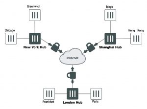
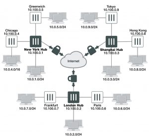
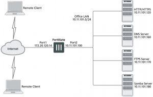
The topology of a VPN for Microsoft Windows dialup clients is very similar to the topology for FortiClient Endpoint Security clients.


Example FortiGate VPN configuration with Microsoft clients

example-fortigate-vpn-configuration

For users, the difference is that instead of installing and using the FortiClient application, they configure a network connection using the software built into the Microsoft Windows operating system. Starting in FortiOS 4.0

MR2, you can configure a FortiGate unit to work with unmodified Microsoft VPN client software.


Layer 2 Tunneling Protocol (L2TP)

L2TP is a tunneling protocol published in 1999 that is used with VPNs, as the name suggests. Microsoft Windows operating system has a built-in L2TP client starting since Windows 2000. Mac OS X 10.3 system and higher also have a built-in client.

L2TP provides no encryption and used UDP port 1701. IPsec is used to secure L2TP packets. The initiator of the L2TP tunnel is called the L2TP Access Concentrator (LAC).

L2TP and IPsec is supported for native Windows XP, Windows Vista and Mac OSX native VPN clients. However, in Mac OSX (OSX 10.6.3, including patch releases) the L2TP feature does not work properly on the Mac OS side.


Assumptions

The following assumptions have been made for this example:

  • L2TP protocol traffic is allowed through network firewalls (TCP and UDP port 1701)
  • User has Microsoft Windows 2000 or higher — a Windows version that supports L2TP


Configuring the FortiGate unit

To configure the FortiGate unit, you must:

  • Configure LT2P users and firewall user group.
  • Configure the L2TP VPN, including the IP address range it assigns to clients.
  • Configure an IPsec VPN with encryption and authentication settings that match the Microsoft VPN client.
  • Configure security policies.


Configuring LT2P users and firewall user group

Remote users must be authenticated before they can request services and/or access network resources through the VPN. The authentication process can use a password defined on the FortiGate unit or an established external authentication mechanism such as RADIUS or LDAP.


Creating user accounts

You need to create user accounts and then add these users to a firewall user group to be used for L2TP authentication. The Microsoft VPN client can automatically send the user’s Window network logon credentials. You might want to use these for their L2TP user name and password.


To create a user account – web-based manager

1. Go to User & Device > User Definition and select Create New.

2. Enter the User Name.

3. Do one of the following:

  • Select Password and enter the user’s assigned password.
  • Select Match user on LDAP server, Match user on RADIUS server, or Match user onTACACS+ server and select the authentication server from the list. The authentication server must be already configured on the FortiGate unit.

4. Select OK.


To create a user account – CLI

To create a user account called user1 with the password 123_user, enter:

config user local edit user1

set type password

set passwd “123_user” set status enable

end


Creating a user group

When clients connect using the L2TP-over-IPsec VPN, the FortiGate unit checks their credentials against the user group you specify for L2TP authentication. You need to create a firewall user group to use for this purpose.


To create a user group – web-based manager

1. Go to User & Device > User Groups, select Create New, and enter the following:

Name                                           Type or edit the user group name (for example, L2TP_group).

Type                                            Select Firewall.

Available Users/Groups           The list of Local users, RADIUS servers, LDAP servers, TACACS+ servers, or PKI users that can be added to the user group. To add a member to this list, select the name and then select the right arrow button.

Members                                    The list of Local users, RADIUS servers, LDAP servers, TACACS+ servers, or PKI users that belong to the user group. To remove a member, select the name and then select the left arrow button.

2. Select OK.


To create a user group – CLI

To create the user group L2TP_group and add members User_1, User_2, and User_3, enter:


config user group edit L2TP_group

set group-type firewall

set member User_1 User_2 User_3 end


Configuring L2TP

You can only configure L2TP settings in the CLI. As well as enabling L2TP, you set the range of IP address values that are assigned to L2TP clients and specify the user group that can access the VPN. For example, to allow access to users in the L2TP_group and assign them addresses in the range 192.168.0.50 to 192.168.0.59, enter:


config vpn l2tp

set sip 192.168.0.50 set eip 192.168.0.59 set status enable

set usrgrp “L2TP_group” end


One of the security policies for the L2TP over IPsec VPN uses the client address range, so you need also need to create a firewall address for that range. For example,


config firewall address edit L2TPclients

set type iprange

set start-ip 192.168.0.50 set end-ip 192.168.0.59

end


Alternatively, you could define this range in the web-based manager.


Configuring IPsec

The Microsoft VPN client uses IPsec for encryption. The configuration needed on the FortiGate unit is the same as for any other IPsec VPN with the following exceptions.

  • Transport mode is used instead of tunnel mode.
  • The encryption and authentication proposals must be compatible with the Microsoft client.

Whether Transport mode is required depends on the configuration of the peer device (typically an old Windows device, since newer versions of Windows don’t require IPsec and L2TP—they can run IPsec natively).

When configuring L2TP, do not name the VPN “L2TP” as that will result in a conflict.

L2TP over IPsec is supported on the FortiGate unit for both policy-based and route-based configurations, but the following example is policy-based.


Configuring Phase 1 – web-based manager

1. Go to VPN > IPsec Tunnels and create the new custom tunnel or edit an existing tunnel.

2. Edit the Phase 1 Proposal (if it is not available, you may need to click the Convert to Custom Tunnel button).

Name                                           Enter a name for this VPN, dialup_p1 for example.

Remote Gateway                       Dialup User

Local Interface                          Select the network interface that connects to the Internet. For example, port1.

Mode                                           Main (ID protection)

Authentication Method            Preshared Key

Preshared Key                          Enter the preshared key. This key must also be entered in the Microsoft VPN client.

Advanced                                   Select Advanced to enter the following information.

Phase 1 Proposal                              Enter the following Encryption/Authentication pairs:

AES256-MD5, 3DES-SHA1, AES192-SHA1

DiffieHellman Group               2

NAT Traversal                            Enable

Dead Peer Detection                 Enable


Configuring Phase 1 – CLI

To create a Phase 1 configuration called dialup_p1 on a FortiGate unit that has port1 connected to the Internet, you would enter:

config vpn ipsec phase1 edit dialup_p1

set type dynamic

set interface port1 set mode main

set psksecret ********

set proposal aes256-md5 3des-sha1 aes192-sha1 set dhgrp 2

set nattraversal enable

set dpd [disable | on-idle | on-demand]

end


It is worth noting here that the command config vpn ipsec phase1 is used rather than config vpn ipsec phase1-interface because this configuration is policy-based and not route-based.


Configuring Phase 2 – web-based manager

1. Open the Phase 2 Selectors panel.

2. Enter the following information and then select OK.

Phase 2 Proposal                              Enter the following Encryption/Authentication pairs:

AES256-MD5, 3DES-SHA1, AES192-SHA1

Enable replay detection           Enable

Enable perfect forward secrecy (PFS) Disable

Keylife                                        3600 seconds

3. Make this a transport-mode VPN. You must use the CLI to do this. If your Phase 2 name is dialup_p2, you would enter:

config vpn ipsec phase2 edit dialup_p2

set encapsulation transport-mode end


Configuring Phase 2 – CLI

To configure a Phase 2 to work with your phase_1 configuration, you would enter:

config vpn ipsec phase2 edit dialup_p2

set phase1name dialup_p1

set proposal aes256-md5 3des-sha1 aes192-sha1 set replay enable

set pfs disable

set keylifeseconds 3600

set encapsulation transport-mode end

Once again, note here that the command config vpn ipsec phase2 is used rather than config vpn ipsec phase2-interface because this configuration is policy-based and not route-based.


Configuring security policies

The security policies required for L2TP over IPsec VPN are:

  • An IPsec policy, as you would create for any policy-based IPsec VPN
  • A regular ACCEPT policy to allow traffic from the L2TP clients to access the protected network


Configuring the IPsec security policy – web-based manager

1. Go to System > Feature Select and enable Policy-based IPsec VPN.

2. Go to Policy & Objects > IPv4 Policy and select Create New.

3. Set the Action to IPsec and enter the following information:

Incoming Interface                   Select the interface that connects to the private network behind this

FortiGate unit.

Source Address                        All

Outgoing Interface                   Select the FortiGate unit’s public interface.

Destination Address                 All

VPN Tunnel                                Select Use Existing and select the name of the Phase 1 configuration that you created. For example, dialup_p1. See Configuring IPsec on page 1781.

Allow traffic to be initiated from the remote site enable

4. Select OK.


Configuring the IPsec security policy – CLI

If your VPN tunnel (Phase 1) is called dialup_p1, your protected network is on port2, and your public interface is port1, you would enter:

config firewall policy edit 0

set srcintf port2 set dstintf port1 set srcaddr all set dstaddr all set action ipsec

set schedule always set service all

set inbound enable

set vpntunnel dialup_p1 end


Configuring the ACCEPT security policy – web-based manager

1. Go to Policy & Objects > IPv4 Policy and select Create New.

2. Leave the Policy Type as Firewall and leave the Policy Subtype as Address.

3. Enter the following information and select OK:

Incoming Interface                   Select the FortiGate unit’s public interface.

Source Address                        Select the firewall address that you defined for the L2TP clients.

Outgoing Interface                   Select the interface that connects to the private network behind this FortiGate unit.

Destination Address                 All

Action                                         ACCEPT


Configuring the ACCEPT security policy – CLI

If your public interface is port1, your protected network is on port2, and L2TPclients is the address range that L2TP clients use, you would enter:

config firewall policy edit 1

set srcintf port1 set dstintf port2

set srcaddr L2TPclients set dstaddr all

set action accept set schedule always set service all

end


Configuring the Windows PC

Configuration of the Windows PC for a VPN connection to the FortiGate unit consists of the following:

1. In Network Connections, configure a Virtual Private Network connection to the FortiGate unit.

2. Ensure that the IPSEC service is running.

3. Ensure that IPsec has not been disabled for the VPN client. It may have been disabled to make the Microsoft VPN compatible with an earlier version of FortiOS.

The instructions in this section are based on Windows XP. Other versions of Windows may vary slightly.


To configure the network connection

1. Open Network Connections.

This is available through the Control Panel.

2. Double-click New Connection Wizard and Select Next.

3. Select Connect to the network at my workplace.

4. Select Next.

5. Select Virtual Private Network connection and select Next.

6. In the Company Name field, enter a name for the connection and select Next.

7. Select Do not dial the initial connection and then select Next.

8. Enter the public IP address or FQDN of the FortiGate unit and select Next.

9. Optionally, select Add a shortcut to this connection to my desktop.

10. Select Finish.

The Connect dialog opens on the desktop.

11. Select Properties and then select the Security tab.

12. Select IPsec Settings.

13. Select Use pre-shared key for authentication, enter the preshared key that you configured for your VPN, and select OK.

14. Select OK.


To check that the IPSEC service is running

1. Open Administrative Tools through the Control Panel.

2. Double-click Services.

3. Look for IPSEC Services. Confirm that the Startup Type is Automatic and Status is set to Started. If needed, double-click IPSEC Services to change these settings.


To check that IPsec has not been disabled

1. Select Start > Run.

2. Enter regedit and select OK.

3. Find the Registry key HKEY_LOCAL_MACHINE\SYSTEM\CurrentControlSet\Services\RasMan\Parameters

4. If there is a ProhibitIPsec value, it must be set to 0.


Troubleshooting

This section describes some checks and tools you can use to resolve issues with L2TP-over-IPsec VPNs. This section includes:

  • Quick checks
  • Mac OS X and L2TP
  • Setting up logging
  • Using the FortiGate unit debug commands


Quick checks

The table below is a list of common L2TP over IPsec VPN problems and the possible solutions.


Problem                                   What to check

IPsec tunnel does not come up.

Check the logs to determine whether the failure is in Phase 1 or Phase 2.

Check the settings, including encapsulation setting, which must be trans- port-mode.

Check the user password.

Confirm that the user is a member of the user group assigned to L2TP. On the Windows PC, check that the IPsec service is running and has not been disabled. See Troubleshooting on page 1786.


Tunnel connects, but there is no communication.

Did you create an ACCEPT security policy from the public network to the protected network for the L2TP clients? See Troubleshooting on page 1786.


Mac OS X and L2TP

FortiOS allows L2TP connections with empty AVP host names and therefore Mac OS X L2TP connections can connect to the FortiGate.

Prior to FortiOS 4.0 MR3, FortiOS refused L2TP connections with empty AVP host names in compliance with RFC 2661 and RFC 3931.


Setting up logging

L2TP logging must be enabled to record L2TP events. Alert email can be configured to report L2TP errors.


To configure FortiGate logging for L2TP over IPsec

1. Go to Log & Report > Log Settings.

2. Select Event Log.

3. Select the VPN activity event check box.

4. Select Apply.


To view FortiGate logs

1. Go to Log & Report > VPN Events.

2. Select the Log location if required.

3. After each attempt to start the L2TP over IPsec VPN, select Refresh to view logged events.


Using the FortiGate unit debug commands


To view debug output for IKE and L2TP

1. Start an SSH or Telnet session to your FortiGate unit.

2. Enter the following CLI commands

diagnose debug application ike -1 diagnose debug application l2tp -1 diagnose debug enable

3. Attempt to use the VPN and note the debug output in the SSH or Telnet session.

4. Enter the following command to reset debug settings to default:

diagnose debug reset


To use the packet sniffer

1. Start an SSH or Telnet session to your FortiGate unit.

2. Enter the following CLI command

diagnose sniffer packet any icmp 4

3. Attempt to use the VPN and note the debug output.

4. Enter Ctrl-C to end sniffer operation.


Typical L2TP over IPsec session startup log entries – raw format

2010-01-11 16:39:58 log_id=0101037127 type=event subtype=ipsec pri=notice vd=”root” msg=”progress IPsec Phase 1″ action=”negotiate” rem_ip=172.20.120.151 loc_ip=172.20.120.141 rem_port=500 loc_port=500 out_ intf=”port1″ cookies=”5f6da1c0e4bbf680/d6a1009eb1dde780″ user=”N/A” group=”N/A” xauth_user=”N/A” xauth_ group=”N/A” vpn_tunnel=”dialup_p1″ status=success init=remote mode=main dir=outbound stage=1 role=responder result=OK

2010-01-11 16:39:58 log_id=0101037127 type=event subtype=ipsec pri=notice vd=”root” msg=”progress IPsec Phase 1″ action=”negotiate” rem_ip=172.20.120.151 loc_ip=172.20.120.141 rem_port=500 loc_port=500 out_ intf=”port1″ cookies=”5f6da1c0e4bbf680/d6a1009eb1dde780″ user=”N/A” group=”N/A” xauth_user=”N/A” xauth_ group=”N/A” vpn_tunnel=”dialup_p1″ status=success init=remote mode=main dir=outbound stage=2 role=responder result=OK

2010-01-11 16:39:58 log_id=0101037127 type=event subtype=ipsec pri=notice vd=”root” msg=”progress IPsec Phase 1″ action=”negotiate” rem_ip=172.20.120.151 loc_ip=172.20.120.141 rem_port=500 loc_port=500 out_ intf=”port1″ cookies=”5f6da1c0e4bbf680/d6a1009eb1dde780″ user=”N/A” group=”N/A” xauth_user=”N/A” xauth_ group=”N/A” vpn_tunnel=”dialup_p1″ status=success init=remote mode=main dir=inbound stage=3 role=responder result=DONE

2010-01-11 16:39:58 log_id=0101037127 type=event subtype=ipsec pri=notice vd=”root” msg=”progress IPsec Phase 1″ action=”negotiate” rem_ip=172.20.120.151 loc_ip=172.20.120.141 rem_port=500 loc_port=500 out_ intf=”port1″ cookies=”5f6da1c0e4bbf680/d6a1009eb1dde780″ user=”N/A” group=”N/A” xauth_user=”N/A” xauth_ group=”N/A” vpn_tunnel=”dialup_p1_0″ status=success init=remote mode=main dir=outbound stage=3 role=responder result=DONE

2010-01-11 16:39:58 log_id=0101037129 type=event subtype=ipsec pri=notice vd=”root” msg=”progress IPsec Phase 2″ action=”negotiate” rem_ip=172.20.120.151 loc_ip=172.20.120.141 rem_port=500 loc_port=500 out_ intf=”port1″ cookies=”5f6da1c0e4bbf680/d6a1009eb1dde780″ user=”N/A” group=”N/A” xauth_user=”N/A” xauth_group=”N/A” vpn_tunnel=”dialup_p1_0″ status=success init=remote mode=quick dir=outbound stage=1 role=responder result=OK

2010-01-11 16:39:58 log_id=0101037133 type=event subtype=ipsec pri=notice vd=”root” msg=”install IPsec SA” action=”install_sa” rem_ip=172.20.120.151 loc_ip=172.20.120.141 rem_port=500 loc_port=500 out_ intf=”port1″ cookies=”5f6da1c0e4bbf680/d6a1009eb1dde780″ user=”N/A” group=”N/A” xauth_user=”N/A” xauth_ group=”N/A” vpn_tunnel=”dialup_p1_0″ role=responder in_spi=61100fe2 out_spi=bd70fca1

2010-01-11 16:39:58 log_id=0101037139 type=event subtype=ipsec pri=notice vd=”root” msg=”IPsec Phase 2 status change” action=”phase2-up” rem_ip=172.20.120.151 loc_ip=172.20.120.141 rem_port=500 loc_port=500 out_intf=”port1″ cookies=”5f6da1c0e4bbf680/d6a1009eb1dde780″ user=”N/A” group=”N/A” xauth_user=”N/A” xauth_group=”N/A” vpn_tunnel=”dialup_p1_0″ phase2_name=dialup_p2

2010-01-11 16:39:58 log_id=0101037138 type=event subtype=ipsec pri=notice vd=”root” msg=”IPsec connection status change” action=”tunnel-up” rem_ip=172.20.120.151 loc_ip=172.20.120.141 rem_port=500 loc_port=500 out_intf=”port1″ cookies=”5f6da1c0e4bbf680/d6a1009eb1dde780″ user=”N/A” group=”N/A” xauth_ user=”N/A” xauth_group=”N/A” vpn_tunnel=”dialup_p1_0″ tunnel_ip=172.20.120.151 tunnel_id=1552003005 tunnel_type=ipsec duration=0 sent=0 rcvd=0 next_stat=0 tunnel=dialup_p1_0

2010-01-11 16:39:58 log_id=0101037129 type=event subtype=ipsec pri=notice vd=”root” msg=”progress IPsec Phase 2″ action=”negotiate” rem_ip=172.20.120.151 loc_ip=172.20.120.141 rem_port=500 loc_port=500 out_ intf=”port1″ cookies=”5f6da1c0e4bbf680/d6a1009eb1dde780″ user=”N/A” group=”N/A” xauth_user=”N/A” xauth_ group=”N/A” vpn_tunnel=”dialup_p1_0″ status=success init=remote mode=quick dir=inbound stage=2 role=responder result=DONE

2010-01-11 16:39:58 log_id=0101037122 type=event subtype=ipsec pri=notice vd=”root” msg=”negotiate IPsec Phase 2″ action=”negotiate” rem_ip=172.20.120.151 loc_ip=172.20.120.141 rem_port=500 loc_port=500 out_ intf=”port1″ cookies=”5f6da1c0e4bbf680/d6a1009eb1dde780″ user=”N/A” group=”N/A” xauth_user=”N/A” xauth_ group=”N/A” vpn_tunnel=”dialup_p1_0″ status=success role=responder esp_transform=ESP_3DES esp_auth=HMAC_ SHA1

2010-01-11 16:39:58 log_id=0103031008 type=event subtype=ppp vd=root pri=information action=connect status=success msg=”Client 172.20.120.151 control connection started (id 805), assigned ip 192.168.0.50″ 2010-01-11 16:39:58 log_id=0103029013 type=event subtype=ppp vd=root pri=notice pppd is started

2010-01-11 16:39:58 log_id=0103029002 type=event subtype=ppp vd=root pri=notice user=”user1″ local=172.20.120.141 remote=172.20.120.151 assigned=192.168.0.50 action=auth_success msg=”User ‘user1’ using l2tp with authentication protocol MSCHAP_V2, succeeded”

2010-01-11 16:39:58 log_id=0103031101 type=event subtype=ppp vd=root pri=information action=tunnel-up tunnel_id=1645784497 tunnel_type=l2tp remote_ip=172.20.120.151 tunnel_ip=192.168.0.50 user=”user1″ group=”L2TPusers” msg=”L2TP tunnel established”


Having trouble configuring your Fortinet hardware or have some questions you need answered? Check Out The Fortinet Guru Youtube Channel! Want someone else to deal with it for you? Get some consulting from Fortinet GURU!