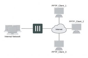
FortiGate unit as a PPTP server
In the most common Internet scenario, the PPTP client connects to an ISP that offers PPP connections with dynamically-assigned IP addresses. The ISP forwards PPTP packets to the Internet, where they are routed to the FortiGate unit.
FortiGate unit as a PPTP server

If the FortiGate unit will act as a PPTP server, there are a number of steps to complete:
- Configure user authentication for PPTP clients.
- Enable PPTP.
- Specify the range of addresses that are assigned to PPTP clients when connecting
- Configure the security policy.
Configuring user authentication for PPTP clients
To enable authentication for PPTP clients, you must create user accounts and a user group to identify the PPTP clients that need access to the network behind the FortiGate unit. Within the user group, you must add a user for each PPTP client.
You can choose to use a plain text password for authentication or forward authentication requests to an external RADIUS, LDAP, or TACACS+ server. If password protection will be provided through a RADIUS, LDAP, or TACACS+ server, you must configure the FortiGate unit to forward authentication requests to the authentication server.
This example creates a basic user/password combination.
Configuring a user account
To add a local user – web-based manager
1. Go to User & Device > User > User Definition and select Create New.
2. Select Local User
3. Enter a User Name.
4. Enter a Password for the user. The password should be at least six characters.
5. Select OK.
To add a local user – CLI
config user local edit <username>
set type password
set passwd <password>
end
Configuring a user group
To ease configuration, create user groups that contain users in similar categories or departments.
To create a user group – web-based manager
1. Go to User & Device > User > User Group and select Create New.
2. Enter a Name for the group.
3. Select the Type of Firewall.
4. From the Available Users list, select the required users and select the right-facing arrow to add them to the
Members list.
5. Select OK.
To create a user group – CLI
config user group edit <group_name>
set group-type firewall set member <user_names>
end
Enabling PPTP and specifying the PPTP IP address range
The PPTP address range specifies the range of addresses reserved for remote PPTP clients. When a PPTP client connects to the FortiGate unit, the client is assigned an IP address from this range. Afterward, the FortiGate unit uses the assigned address to communicate with the PPTP client.
The address range that you reserve can be associated with private or routable IP addresses. If you specify a private address range that matches a network behind the FortiGate unit, the assigned address will make the PPTP client appear to be part of the internal network.
PPTP requires two IP addresses, one for each end of the tunnel. The PPTP address range is the range of addresses reserved for remote PPTP clients. When the remote PPTP client establishes a connection, the FortiGate unit assigns an IP address from the reserved range of IP addresses to the client PPTP interface or retrieves the assigned IP address from the PPTP user group. If you use the PPTP user group, you must also define the FortiGate end of the tunnel by entering the IP address of the unit in Local IP (web-based manager) or local-ip (CLI). The PPTP client uses the assigned IP address as its source address for the duration of the connection.
PPTP configuration is only available through the CLI. In the example below, PPTP is enabled with the use of an IP range of 182.168.1.1 to 192.168.1.10 for addressing and the user group is hr_staff.
The start and end IPs in the PPTP address range must be in the same 24-bit subnet, for example, 192.168.1.1 – 192.168.1.254.
config vpn pptp
set status enable set ip-mode range
set eip 192.168.1.10 set sip 192.168.1.1 set usrgrp hr_staff
end
In this example, PPTP is enabled with the use of a user group for addressing, where the IP address of the PPTP server is 192.168.1.2 and the user group is hr_admin.
config vpn pptp
set status enable set ip-mode range
set local-ip 192.168.2.1 set usrgrp hr_admin
end
Adding the security policy
The security policy specifies the source and destination addresses that can generate traffic inside the PPTP tunnel and defines the scope of services permitted through the tunnel. If a selection of services are required, define a service group.
To configure the firewall for the PPTP tunnel – web-based manager
1. Go to Policy & Objects > Policy > IPv4 or Policy & Objects > Policy > IPv6 and select Create New.
2. Complete the following and select OK:
Incoming Interface The FortiGate interface connected to the Internet.
Source Address Select the name that corresponds to the range of addresses that you reserved for PPTP clients.
Outgoing Interface The FortiGate interface connected to the internal network.
Destination Address Select the name that corresponds to the IP addresses behind the FortiGate unit.
Schedule always
Service ALL
Action ACCEPT
To configure the firewall for the PPTP tunnel – CLI
config firewall policy or config firewall policy6 edit 1
set srcintf <interface to internet>
set dstintf <interface to internal network>
set srcaddr <reserved_range>
set dstaddr <internal_addresses>
set action accept set schedule always set service ALL
end
Configuring the FortiGate unit for PPTP VPN
To arrange for PPTP packets to pass through the FortiGate unit to an external PPTP server, perform the following tasks in the order given:
- Configure user authentication for PPTP clients.
- Enable PPTP on the FortiGate unit and specify the range of addresses that can be assigned to PPTP clients when they connect.
- Configure PPTP pass through on the FortiGate unit.
Configuring the FortiGate unit for PPTP pass through
To forward PPTP packets to a PPTP server on the network behind the FortiGate unit, you need to perform the following configuration tasks on the FortiGate unit:
- Define a virtual IP address that points to the PPTP server.
- Create a security policy that allows incoming PPTP packets to pass through to the PPTP server.
The address range is the external (public) ip address range which requires access to the internal PPTP server through the FortiGate virtual port-forwarding firewall.
IP addresses used in this document are fictional and follow the technical doc- umentation guidelines specific to Fortinet. Real external IP addresses are not used.
Configuring a virtual IP address
The virtual IP address will be the address of the PPTP server host.
To define a virtual IP for PPTP pass through – web-based manager
1. Go to Policy & Objects > Objects > Virtual IPs.
2. Select Create New.
3. Choose the VIP Type.
4. Enter the name of the VIP, for example, PPTP_Server.
5. Select the External Interface where the packets will be received for the PPTP server.
6. Enter the External IP Address for the VIP.
7. Select Port Forwarding.
8. Set the Protocol to TCP.
9. Enter the External Service Port of 1723, the default for PPTP.
10. Enter the Map to Port to 1723.
11. Select OK.
To define a virtual IP for PPTP pass through – web-based manager
config firewall vip or config firewall vip6 edit PPTP_Server
set extintf <interface> set extip <ip_address> set portforward enable set protocol tcp
set extport 1723
set mappedport 1723
set mappedip <destination IP address range>
end
You can also use config firewall vip46 to define a virtual IP from an IPv4 address to an IPv6 address or config firewall vip64 to define a virtual IP from an IPv6 address to an IPv4 address.
Configuring a port-forwarding security policy
To create a port-forwarding security policy for PPTP pass through you must first create an address range reserved for the PPTP clients.
To create an address range – web-based manager
1. Go to Policy & Objects > Objects > Addresses and select Create New.
2. Select a Category.
3. Enter a Name for the range, for example, External_PPTP.
4. Select a Type of Subnet/IP Range.
5. Enter the IP address range.
6. Select the Interface to the Internet.
7. Select OK.
To create an address range – CLI
config firewall address OR config firewall address6 edit External_PPTP
end
set type ip_range
set start-ip <ip_address>
set end-ip <ip_address>
set associated-interface <internet_interface>
With the address set, you can add the security policy.
To add the security policy – web-based manager
1. Go to Policy & Objects > Policy > IPv4 or Policy & Objects > Policy > IPv6 and select Create New.
2. Complete the following and select OK:
Incoming Interface The FortiGate interface connected to the Internet.
Source Address Select the address range created in the previous step.
Outgoing Interface The FortiGate interface connected to the PPTP server.
Destination Address Select the VIP address created in the previous steps.
Schedule always
Service PPTP
Action ACCEPT
To add the security policy – CLI
config firewall policy or config firewall policy6 edit <policy_number>
set srcintf <interface to internet>
set dstintf <interface to PPTP server>
set srcaddr <address_range>
set dstaddr <PPTP_server_address>
set action accept set schedule always set service PPTP
end
Testing PPTP VPN connections
To confirm that a PPTP VPN between a local network and a dialup client has been configured correctly, at the dialup client, issue a ping command to test the connection to the local network. The PPTP VPN tunnel initializes when the dialup client attempts to connect.
Logging VPN events
PPTP VPN, activity is logged when enabling VPN logging. The FortiGate unit connection events and tunnel status I thi(up/down) are logged.
To log VPN events
1. Go to Log & Report > Log Config > Log Settings.
2. Enable the storage of log messages to one or more locations.
3. Select VPN activity event.
4. Select Apply.
To view event logs
1. Go to Log & Report > Event Log > VPN.
2. If the option is available from the Log Type list, select the log file from disk or memory.