Routing-mode WAN link
Configuration of a routing-mode WAN link starts from selecting and enabling the WAN link on Web UI (see Start to configure a WAN link in Configuring your WAN and DMZ), and select Routing Mode from the WAN Type dropdown menu in Basic Setting panel. After that, you start configuring the following settings: IPv4-based routing-mode WAN link l Basic setting and at least one IPv4 basic subnet are necessary.
- IPv4 static routing subnet is for your option.
- IPv4/IPv6 Dual-stack routing-mode WAN link
- Basic setting, one IPv4 basic subnet and one IPv6 basic subnet are necessary.
- IPv4/IPv6 static routing subnets are for your options.
Basic Setting
Besides the WAN Type, the rest setting fields of Basic Setting of a routing-mode WAN link are as followings:
| WAN Port |
|
A FortiWAN’s network port used to connect the WAN link with the FortiWAN (you need to physically install the network cable to this port for the WAN link). All the physical and VLAN ports that are mapped to WAN (see Aggregated, Redundant, VLAN Ports and Port Mapping) are listed here for your options. The WAN link field is unrelated to the WAN port. For example, you can install WAN link 1 to WAN Port3, or WAN link 3 to WAN Port 1. (See WAN link and WAN port). |
| Down/Up Stream |
The WAN link’s transfer speed at which you can download/upload data from/to the Internet. Please input the value in Kbps, e.g. 10240Kbps/640Kbps. FortiWAN Bandwidth Management’s default inbound and outbound classes use the two values actively to limit the download and upload rates on the WAN link (see Bandwidth Management). |
| Down/Up Stream Threshold |
Specify upstream/downstream (Kbps) threshold to the WAN link. WAN links with traffic exceeding the thresholds will be considered as failed.
FortiWAN’s Auto Routing and Multihoming will ignore the WAN links failed
by exceeding traffic while distributing traffic over WAN links, if the Threshold function is enabled in their load-balancing policies (See Outbound Load Balancing and Failover (Auto Routing) and Inbound Load Balancing and Failover (Multihoming)).
Leave it blank or zero if you do not apply threshold to the WAN link. |
| MTU |
(Maximum Transmission unit) refers to the size of the largest packet or frame that a given layer of a communications protocol can pass onwards on the WAN port. It allows dividing the packet into pieces, each small enough to pass over a single link. It is set to 1500 by default. |
| IPv4 Gateway |
IPv4 address of the default gateway of the WAN link. This field is mandatory. |
| IPv6 Gateway |
IPv6 address of the default gateway of the WAN link. This field is optional. Ignore it for IPv4-based links or configure it for IPv4/IPv6 dual stack links. |
Static routing information
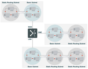
As mentioned previously, FortiWAN requires the correct routing information to deliver packets among the connected near WAN, DMZ and LAN networks. Configurations of basic subnets and static routing subnets of a WAN link are the routing information for the FortiWAN.
A routing-mode WAN link is attached with an IP network which should be deployed as a basic subnet to the WAN link. Since localhost of the WAN port is a part of the subnet, at least one basic subnet is necessary for configuring a routing-mode WAN link. For the reason, IP(s) on Localhost and Netmask fields of a routing-mode WAN link are contained in configuration of Basic Subnet, rather than Basic Setting.
IPv4/IPv6 Basic Subnet
Basic subnets are the subnets connecting directly to FortiWAN. A DMZ must be associated with a WAN link, therefore, basic subnet of a WAN link can be divided into four types according to combination of WAN and DMZ:
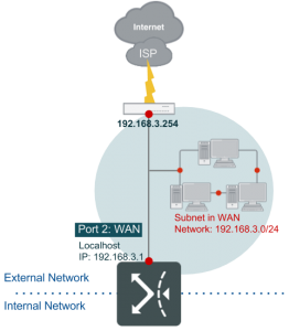
- Subnet in WAN: A subnet deployed in WAN. This type requires at least one IP for localhost of the WAN port, and the rest of the subnet can be used for hosts in WAN (near WAN).
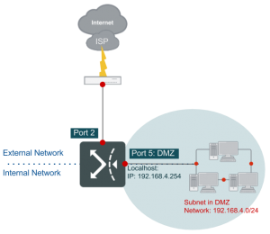
- Subnet in DMZ: A subnet deployed in DMZ. This type requires at least one IP for localhost of the DMZ port, and the rest of the subnet can be used for hosts in DMZ.
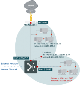
- Subnet in WAN and DMZ: A subnet deployed in two segments, WAN and DMZ. Proxy ARP combines the two segments into a logic segment for the IP subnet (see ). Proxy ARP logically combines the specified WAN port and DMZ port into a logical port. This type requires at least one IP for localhost of the WAN port, and the rest of the subnet can be used for hosts in WAN (near WAN) and DMZ.
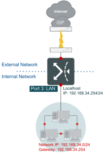
- Subnet on Localhost: A subnet deployed on the localhost of a WAN port (This is not supported for IPv6 basci
subnets). All the IP addresses of the subnet will be deployed on the WAN port.
A subnet in WAN and DMZ might be the most practical deployment for a routing-mode WAN link. If the ISP provides only one network with your IPv4 WAN link (this is the most general case for a routing-mode link), you can deploy it as any of the subnet types but a subnet in DMZ. Remember, at least one IP address must be assigned to localhost of a WAN port for the IPv4 link, therefore, at least one subnet must be associated with the WAN port. If you get more than one network from the ISP with the IPv4 link, you still have to deploy at least one of them as a subnet in WAN, a subnet in WAN and DMZ or a subnet on localhost, but there is not limitation to the rest networks. Briefly, if you are given only one network for the WAN link, you can not deploy it as a subnet in DMZ. As for configuring a dual stack link, similarly, it requires at least one IPv4 network and one IPv6 network get deployed individually as a subnet in WAN, a subnet in WAN and DMZ or a subnet on localhost. Next comes the configuration of basic subnet for each type:
[IPv4/IPv6 Basic Subnet]: Subnet in WAN
Click the add button on the IPv4 Basic Subnet panel or IPv6 Basic Subnet panel to add a configuration, and select Subnet in WAN from the Subnet Type drop-down menu. The rest configuration fields to deploy a IPv4/IPv6 network as a subnet in WAN are as followings:
| IP(s) on Localhost |
The IP address(es) that you want to assign to localhost of the specified WAN port (the WAN port that is specified in Basic Setting panel) for the WAN link. At least one IP address is required here. You can type a range of IP addresses here in format “IPstart-IPend” or click the add button to individually add more IP addresses to the localhost.
Note that the rest IP addresses of the network that are not assigned to the localhost here will be automatically considered as being located in WAN area. |
| Netmask/Prefix Length |
Netmask/Prefix Length of the IPv4/IPv6 network that you are deploying to the WAN link as a subnet in WAN. |
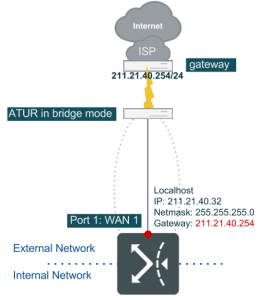
This topology is frequently used for where cluster hosts being deployed in WAN.
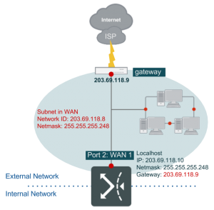
In the this diagram, we have a WAN link attached with a given network that netmask is 255.255.255.248, gateway is 203.69.118.9 and the available IP addresses are 203.69.118.10 – 203.69.118.14. The WAN link is connected to FortiWAN’s Port2 (mapped to a WAN port) with IP address 203.69.118.10 being assigned to the localhost. In this case, FortiWAN will consider that the rest IP addresses 203.69.118.11 – 203.69.118.14 are located in the WAN area (actually, the near WAN) of the WAN link. The following is the configuration for this case:
| Basic Setting |
|
| WAN Port |
Port2 |
| IPv4 Gateway |
203.69.118.9 |
| IPv4 Basic Subnet |
|
| Subnet Type |
Subnet in WAN |
| IP(s) on localhost |
203.69.118.10 |
| Netmask |
255.255.255.248 |
|
|
|
Configuration of the settings implies a route to FortiWAN that any packet destined to 203.69.118.9 – 203.69.118.14 will be directly forwarded through this WAN port, without Auto Routing and Bandwidth
Management processes. In this case, subnet 203.69.118.8/29 (203.69.118.9 – 203.69.118.14) is the near WAN of the link.
[IPv4/IPv6 Basic Subnet]: Subnet in DMZ
Click the add button on the IPv4 Basic Subnet panel or IPv6 Basic Subnet panel to add a configuration, and select Subnet in DMZ from the Subnet Type drop-down menu. The rest configuration fields are as followings:
| IP(s) on Localhost |
The IP address(es) of the IPv4/IPv6 network that you want to assign to localhost of the specified DMZ port (the DMZ port that is specified below) of the WAN link. At least one IP address is required here. You can type a range of IP addresses here in format “IPstart-IPend” or click the add button to individually add more IP addresses to the localhost.
Note that the rest IP addresses of the network that are not assigned to the localhost here will be automatically considered as being located in DMZ area. |
| Netmask/Prefix Length |
Netmask/Prefix Length of the IPv4/IPv6 network that is being deployed as a subnet in DMZ and associated with the WAN link. |
| DMZ Port |
A FortiWAN’s network port used to connect a subnet of the WAN link with the FortiWAN as a DMZ subnet (you need to physically install the network cable to this port for the DMZ subnet). All the physical, logical and VLAN ports that are mapped to DMZ (see Aggregated, Redundant, VLAN Ports and Port Mapping) are listed here for your options. |
| Enable DHCP/DHCP
Relay/SLAAC/DHCPv6
Service |
Click to enable automatic addressing on the specified DMZ port for hosts in the connected IPv4/IPv6 DMZ subnet (see Automatic addressing within a basic subnet for configuration details).
Note that only the IP addresses of the IPv4/IPv6 basic subnet defined here are the candidates for related IP pools of automatic addressing. |
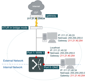
This topology is frequently used for where a cluster of hosts being deployed in DMZ. The following example for a subnet in DMZ is based on the above example that a WAN link with a subnet being deployed in WAN. Please click the [+] button on IPv4/IPv6 Basic Subnet panel to add a subnet to the WAN link. Remember a subnet in DMZ must coexist with a subnet in WAN, a subnet in WAN and DMZ or a subnet on localhost.

As described in the topology, since the cluster of hosts are deployed in DMZ. FortiWAN port5 has to be mapped to DMZ with IP address 140.112.8.9. Thus the hosts in the subnet take the default gateway as 140.112.8.9. In this case, IP addresses 203.69.118.9 – 203.69.118.14 are treated as in near WAN, while IP addresses 140.112.8.9 – 140.112.8.14 in DMZ do not belong to near WAN. Check [Enable DHCP] if hosts in the subnet in DMZ require DHCP service. And enter the starting and ending address in [DHCP Range]. If any host in the subnet uses static IP address, then in [Static Mapping], enter its IP and MAC address. Similarly, if ISP provides another LAN IPv6 subnet, you can deploy it in DMZ. The SLAAC and DHCPv6 in FortiWAN are designed to work together, which SLAAC responses router advertisement (including default gateway and DNS server) to a host and DHCPv6 responses the host an appropriate IPv6 address. Note: FortiWAN assumes that IP addresses that are unlisted in [IP(s) on Localhost] can be used for hosts in the subnet.
In the this diagram, we have another network that ISP provides to the WAN link, which the netmask is
255.255.255.248, gateway is 140.112.8.9 and the available IP addresses are 140.112.8.10 – 140.112.8.14. This network is connected to FortiWAN’s Port5 (mapped to a DMZ port) with IP address 203.69.118.10 being assigned to the localhost. In this case, FortiWAN will consider that the rest IP addresses 203.69.118.11 – 203.69.118.14 are located in the WAN area (actually, the near WAN) of the WAN link. The following is the configuration for this case:
| Basic Setting |
|
| WAN Port |
Port2 |
| IPv4 Gateway |
203.69.118.9 |
| IPv4 Basic Subnet 1 |
|
| Subnet Type |
Subnet in WAN |
| IP(s) on localhost |
203.69.118.10 |
| Netmask |
255.255.255.248 |
| IPv4 Basic Subnet 2 |
|
| Subnet Type |
Subnet in DMZ |
| IP(s) on localhost |
140.112.8.9 |
| Netmask |
255.255.255.248 |
| DMZ Port |
Port5 |
For the details about DHCP, DHCP Relay, SLAAC and DHCPv6, see “Automatic addressing within a basic subnet”.
[IPv4/IPv6 Basic Subnet]: Subnet in WAN and DMZ
Click the add button on the IPv4 Basic Subnet panel or IPv6 Basic Subnet panel to add a configuration, and select Subnet in WAN and DMZ from the Subnet Type drop-down menu. The rest configuration fields are as followings:
| IP(s) on Localhost |
The IP address(es) of the IPv4/IPv6 network that you want to assign to localhost of the specified WAN port (the WAN port that is specified in Basic Setting panel) and DMZ port (the DMZ port that is specified below) of the WAN link. The WAN port and DMZ port will be logically combined for Public IP Passthrough. At least one IP address is required here. You can type a range of IP addresses here in format “IPstart-IPend” or click the add button to individually add more IP addresses to the localhost. |
| IP(s) in WAN |
The IP address(es) of the IPv4/IPv6 network that you want to assign to the WAN area (near WAN) of the WAN link. You can leave it blank, type one IP address or a range of IP addresses (in format “IPstart-IPend” ) here. You can also click the add button to individually add more IP addresses to the near WAN.
Note that the rest IP address(es) of the network that are not assigned to the localhost (above) and WAN (here) will be automatically considered as being located in DMZ. Therefore, no matter how you deploy IP addresses in WAN area, at least one IP address, IP address of gateway of the WAN link (what you set in Basic Setting for IPv4 Gateway and/or IPv6 Gateway), must be contained in this field. |
| Netmask/Prefix Length |
Netmask/Prefix Length of the IPv4/IPv6 network that you are deploying to the WAN link as a subnet in WAN. |
| DMZ Port |
A FortiWAN’s network port used to connect a part of the subnet to the WAN link as segment in DMZ (you need to physically install the network cable to this port for the DMZ subnet). All the physical, logical and VLAN ports that are mapped to DMZ (see Aggregated, Redundant, VLAN Ports and Port Mapping) are listed here for your options. |
| Enable DHCP/DHCP
Relay/SLAAC/DHCPv6
Service |
Click to enable automatic addressing on the specified DMZ port for hosts in the connected IPv4/IPv6 DMZ segment (see Automatic addressing within a basic subnet for configuration details).
Note that only the IP addresses assigned to the DMZ part of the defined basic subnet are the candidates for related IP pools of automatic addressing. |
This topology is frequently found where a cluster of hosts in one subnet are deployed in both WAN side and DMZ side.
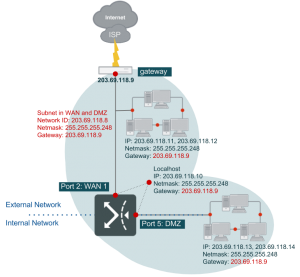
As described in the topology, port2 and port5 are connected in dotted line, indicating an IP range in the same subnet 203.69.118.8/29 spreads across WAN (port2) and DMZ (port5). FortiWAN employs Proxy ARP to connect those hosts becoming in the same network segment (See “Public IP pass through (DMZ Transparent Mode)”).
Note that although IP address 203.69.118.9 has been configured as default gateway in Basic Setting table, you are still required to add it in the field [IP(s) in WAN]. When you select [Subnet in WAN and DMZ] from [Subnet Type], FortiWAN will assume the IP addresses that are unlisted in [IP(s) on Localhost] and [IP(s) in WAN] are all in DMZ. Thus, in this example, except 203.69.118.10, 203.69.118.9 and 203.69.118.11-203.69.118.12, the rest IP addresses of subnet 203.69.118.8/29 are assigned to DMZ for Public IP Pass-through. In this case, IP addresses 203.69.118.9 – 203.69.118.12 in WAN side are treated as in near WAN, while IP addresses 203.69.118.13 – 203.69.118.14 in DMZ side do not belong to near WAN.
Check [Enable DHCP] if hosts in the subnet in DMZ require DHCP service. And enter the starting and ending address in [DHCP Range]. If any host in the subnet uses static IP address, then in [Static Mapping], enter its IP and MAC address. Similarly, the configuration to deploy an IPv6 public subnet in WAN and DMZ.
| Basic Setting |
|
| WAN Port |
Port2 |
| IPv4 Gateway |
203.69.118.9 |
| IPv4 Basic Subnet |
|
| Subnet Type |
Subnet in WAN and DMZ |
| IP(s) on localhost |
203.69.118.10 |
| IP(s) in WAN |
203.69.118.11-203.69.118.12 |
| Netmask |
255.255.255.248 |
| DMZ Port |
Port5 |
For the details about DHCP, DHCP Relay, SLAAC and DHCPv6, see “Automatic addressing within a basic subnet”.
[IPv4/IPv6 Basic Subnet]: Subnet on Localhost
Click the add button on the IPv4 Basic Subnet panel (this subnet type is not supported for IPv6 basic subnets) to add a configuration, and select Subnet on Localhost from the Subnet Type drop-down menu. The rest configuration fields are as followings:
| Network IP |
The network IP of the subnet that you want to assign to localhost of the specified WAN port (the WAN port that is specified in Basic Setting panel). |
| Netmask |
Netmask of the IPv4 subnet that you are deploying to the WAN link as a subnet on localhost. |
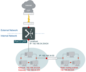
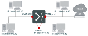
This topology is found where subnet is designated on FortiWAN to better use Virtual Server.
This deployment is much simpler than other subnet types. Except the gateway, all the IP addresses of the subnet are assigned to the WAN port of the WAN link; there is no IP addresses available for deployment in WAN and/or DMZ areas. All of the IP addresses will indicate the associated WAN link to services NAT, Multihoming and Virtual Server. For this example, the configuration just requires 203.69.118.8 and 255.255.255.248 being entered in [Network IP] and [Netmask] respectively.
| Basic Setting |
|
| WAN Port |
Port2 |
| IPv4 Gateway |
203.69.118.9 |
| IPv4 Basic Subnet |
|
| Subnet Type |
Subnet on Localhost |
| Network IP |
203.69.118.8 |
| Netmask |
255.255.255.248 |
Note that, for all of the subnet types described above, the IP addresses (IPv4 or IPv6) specified to field [IP(s) on
Localhost] can be used for NAT to transfer the source IP address of packets to. The first IP address on the list of [IP(s) on Localhost] will be used for the NAT default rules of the WAN link. System generates NAT default rules automatically for a WAN link so that a host with private IP address in LAN can access Internet without setting NAT rules manually. For FortiWAN V4.0.x, system does not generate NAT default rules for IPv6 WAN links, setting NAT rules manually is required (See “NAT”).
IPv4/IPv6 Static Routing Subnets
A WAN link’s static routing subnets are the subnets connected to the WAN link’s basic subnets via routers or L3 switches. The same as those basic subnets, FortiWAN needs the corresponding static route (dynamic routing protocols are not supported for WAN links’ networks), so that FortiWAN can find the path to forward packets to the static routing subnets. Configuring a static routing subnet to a WAN link here implies adding the routing information to FortiWAN. A routing-mode WAN link supports both IPv4 and IPv6 static routing subnets for pure IPv4-based WAN link and IPv4/IPv6 dual stack WAN link. According to the area a subnet deployed in, the static routing subnets of a WAN link are divided into:
- Subnet in WAN: A static routing subnet deployed in WAN, connected to a basic subnet in WAN or basic subnet in WAN and DMZ.
- Subnet in DMZ: A static routing subnet deployed in DMZ, connected to a basic subnet in DMZ or basic subnet in WAN and DMZ.
Next comes a few examples to further illustrate configurations in [Basic Subnet] and [Static Routing Subnet].
[IPv4/IPv6 Static Routing Subnet]: Subnet in WAN
Click the add button on the IPv4 Static Routing Subnet panel or IPv6 Static Routing Subnet panel to add a configuration, and select Subnet in WAN from the Subnet Type drop-down menu. The rest configuration fields are as followings:
| Network IP |
The network IP of the IPv4 static routing subnet that you want to deploy in (near) WAN area of the WAN link. This field is in IPv4 Static Routing Subnet panel. |
| Netmask |
Netmask of the IPv4 static routing subnet that you want to deploy in (near) WAN area of the WAN link. This field is in IPv4 Static Routing Subnet panel. |
| Subnet |
The IPv6 static routing subnet that you want to deploy in (near) WAN area of the WAN link in format such as 2000::123f:0:0:1/32. This field is in IPv6 Static Routing Subnet panel. |
| Gateway |
IPv4/IPv6 address of the gateway (router) connecting a basic subnet with the static routing subnet. This IP address is the path that FortiWAN uses to forward packets destined to the static routing subnet to. This field is in both IPv4 and IPv6 Static Routing Subnet panels. |
| Proxy ARP |
Check to enable Proxy ARP on FortiWAN for the static routing subnet; FortiWAN will answer the ARP queries for a network address that is in the static routing subnet. This field is in IPv4 Static Routing Subnet panel. |
This topology is rarely seen in actual network where static routing subnet is located on the WAN. In other words, the subnet in WAN does not connect to FortiWAN directly, but needs a router instead to transfer packets. In this example, a subnet 202.3.1.8/29 located on the WAN connects to the basic subnet 203.69.118.8/29 via a router (202.3.1.9 and 203.69.118.10). Subnet 202.3.1.8/29 is so that a static routing subnet of the WAN link. Configuration of the static routing subnet indicates the route to FortiWAN for packets destined to subnet 202.3.1.8/29.
As described in the UI, FortiWAN transfers packets to the gateway 203.69.118.10 to deliver them to subnet 202.3.1.8/255.255.255.248.
| Basic Setting |
|
| WAN Port |
Port2 |
| IPv4 Gateway |
203.69.118.9 |
| IPv4 Basic Subnet |
|
| Subnet Type |
Subnet in WAN |
| IP(s) on localhost |
203.69.118.10 |
| Netmask 255.255.255.248 |
| IPv4 Static Routing Subnet |
| Subnet Type Subnet in WAN |
| Network IP 202.3.1.8 |
| Netmask 255.255.255.248 |
| Gateway 203.69.118.10 |
[IPv4/IPv6 Static Routing Subnet]: Subnet in DMZ
Click the add button on the IPv4 Static Routing Subnet panel or IPv6 Static Routing Subnet panel to add a configuration, and select Subnet in DMZ from the Subnet Type drop-down menu. The rest configuration fields are as followings:
| Network IP |
The network IP of the IPv4 static routing subnet that you want to deploy in DMZ area of the WAN link. This field is in IPv4 Static Routing Subnet panel. |
| Netmask |
Netmask of the IPv4 static routing subnet that you want to deploy in DMZ area of the WAN link. This field is in IPv4 Static Routing Subnet panel. |
| Subnet |
The IPv6 static routing subnet that you want to deploy in DMZ area of the WAN link in format such as 2000::123f:0:0:1/32. This field is in IPv6 Static Routing Subnet panel. |
| Gateway |
IPv4/IPv6 address of the gateway (router) connecting a basic subnet with the static routing subnet. This IP address is the path that FortiWAN uses to forward packets destined to the static routing subnet to. This field is in both IPv4 and IPv6 Static Routing Subnet panels. |
| Proxy ARP |
Check to enable Proxy ARP on FortiWAN for the static routing subnet; FortiWAN will answer the ARP queries for a network address that is in the static routing subnet. This field is in IPv4 Static Routing Subnet panel. |
This topology is very similar with the Static Routing Subnet: Subnet in WAN in last example. The only difference is, the subnet is in DMZ area.
As described in the UI, FortiWAN transfers packets to the gateway 203.69.118.14 to deliver them to subnet 139.3.1.8/255.255.255.248
| Basic Setting |
|
| WAN Port |
Port2 |
| IPv4 Gateway |
203.69.118.9 |
| IPv4 Basic Subnet |
|
| Subnet Type |
Subnet in WAN and DMZ |
| IP(s) on localhost |
203.69.118.10 |
| IP(s) in WAN |
203.69.118.11-203.69.118.13 |
| Netmask 255.255.255.248 |
| DMZ Port Port5 |
| IPv4 Static Routing Subnet |
| Subnet Type Subnet in WAN |
| Network IP 202.3.1.8 |
| Netmask 255.255.255.248 |
| Gateway 203.69.118.14 |
See also
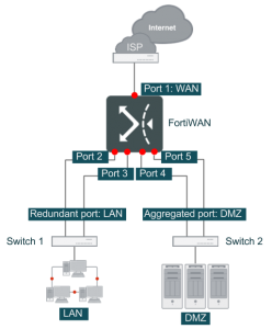
- WAN link and WAN port
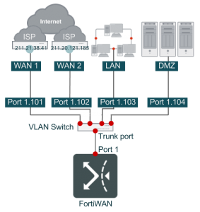
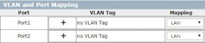
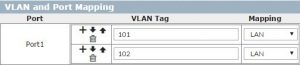
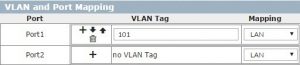
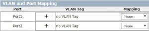
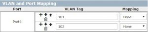
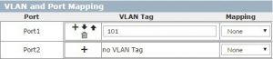
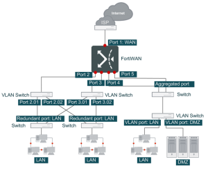
- VLAN and port mapping
- Configurations for VLAN and Port Mapping
- Outbound Load Balancing and Failover (Auto Routing)
- Inbound Load Balancing and Failover (Multihoming)
- Scenarios to deploy subnets
- Public IP pass through (DMZ Transparent Mode)
- IPv6/IPv4 Dual Stack
Having trouble configuring your Fortinet hardware or have some questions you need answered? Check Out The Fortinet Guru Youtube Channel! Want someone else to deal with it for you? Get some consulting from Fortinet GURU!